b. Locate the corresponding DIMM slot on the replacement controller module.
c. Make sure that the DIMM ejector tabs on the DIMM socket are in the open position, and then insert the
DIMM squarely into the socket.
The DIMMs fit tightly in the socket, but should go in easily. If not, realign the DIMM with the socket and
reinsert it.
d. Visually inspect the DIMM to verify that it is evenly aligned and fully inserted into the socket.
e. Repeat these substeps for the remaining DIMMs.
5. Plug the NVDIMM battery into the motherboard.
Make sure that the plug locks down onto the controller module.
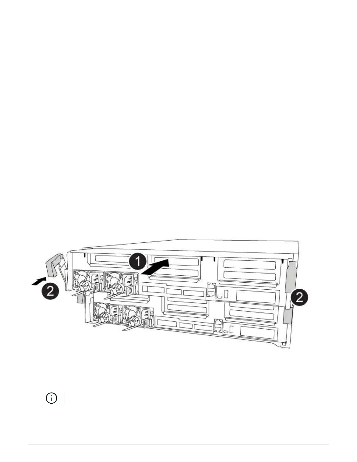
Step 7: Install the controller module
After all of the components have been moved from the impaired controller module to the replacement controller
module, you must install the replacement controller module into the chassis, and then boot it to Maintenance
mode.
You can use the following animation, illustration, or the written steps to install the replacement controller
module in the chassis.
Installing the controller module
1. If you have not already done so, close the air duct.
2. Align the end of the controller module with the opening in the chassis, and then gently push the controller
module halfway into the system.
Do not completely insert the controller module in the chassis until instructed to do so.
3. Cable the management and console ports only, so that you can access the system to perform the tasks in
the following sections.
627