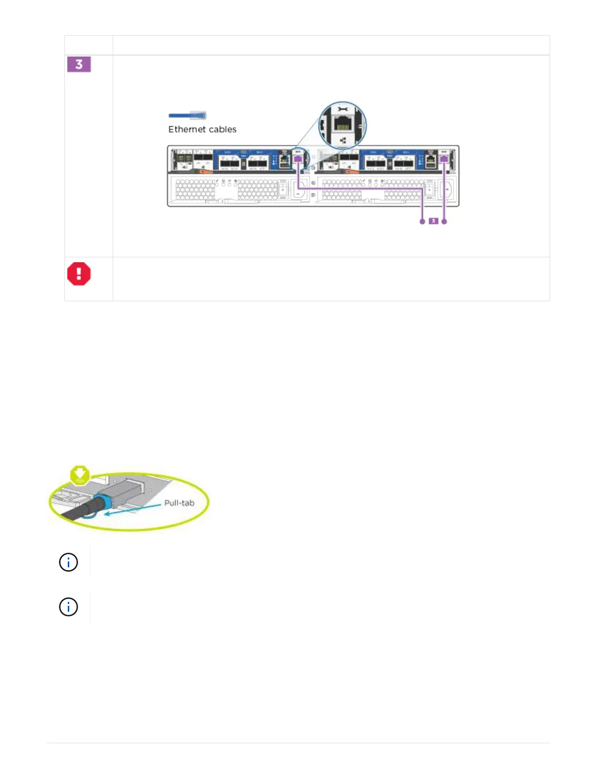
Step Perform on each controller
Cable the e0M ports to the management network switches with the RJ45 cables:
DO NOT plug in the power cords at this point.
2. To complete setting up your system, see
Step 4: Complete system setup and configuration.
Option 2: Cable switched cluster, unified configuration
UTA2 ports and management ports on the controller modules are connected to switches. The cluster
interconnect ports are cabled to the cluster interconnect switches.
Before you begin
Contact your network administrator for information about connecting the system to the switches.
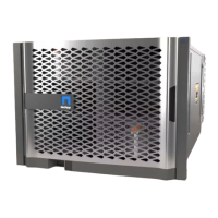
Be sure to check the illustration arrow for the proper cable connector pull-tab orientation.
As you insert the connector, you should feel it click into place; if you do not feel it click, remove
it, turn it around and try again.
If connecting to an optical switch, insert the SFP into the controller port before cabling to the
port.
Steps
1. Use the illustration or the step-by-step instructions to complete the cabling between the controllers and the
switches:
6