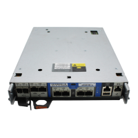
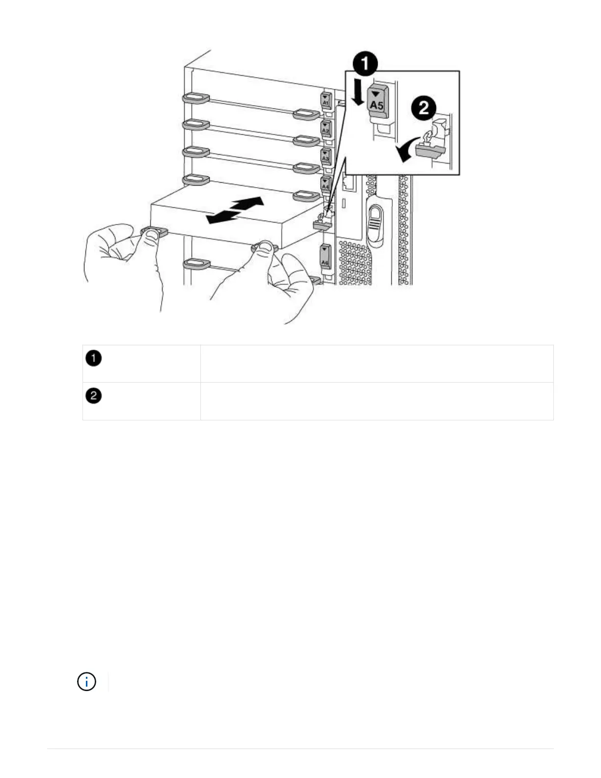
Lettered and numbered I/O cam latch
I/O cam latch completely unlocked
4. Set the I/O module aside.
5. Install the replacement I/O module into the chassis by gently sliding the I/O module into the slot until the
lettered and numbered I/O cam latch begins to engage with the I/O cam pin, and then push the I/O cam
latch all the way up to lock the module in place.
6. Recable the I/O module, as needed.
Step 3: Reboot the controller after PCIe module replacement
After you replace a PCIe module, you must reboot the controller module.
Steps
1.
If the node is at the LOADER prompt, boot the node, responding
y if you see a prompt warning of a system
ID mismatch and asking to override the system ID:
bye
2. If your system is configured to support 10 GbE cluster interconnect and data connections on 40 GbE NICs
or onboard ports, convert these ports to 10 GbE connections by using the
nicadmin convert command
from Maintenance mode.
Be sure to exit Maintenance mode after completing the conversion.
3. Return the node to normal operation:
798
 Loading...