+
Locking tabs
Slide plunger
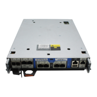
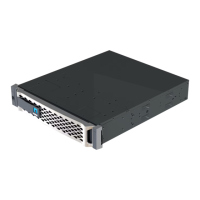
3. Align the end of the controller module with the opening in the chassis, and then gently push the controller
module halfway into the system.
Do not completely insert the controller module in the chassis until instructed to do so.
4. Cable the management and console ports only, so that you can access the system to perform the tasks in
the following sections.
You will connect the rest of the cables to the controller module later in this procedure.
5. Plug the power cord into the power supply, reinstall the power cable locking collar, and then connect the
power supply to the power source.
6. Complete the reinstallation of the controller module:
a. If you have not already done so, reinstall the cable management device.
b. Firmly push the controller module into the chassis until it meets the midplane and is fully seated.
The locking latches rise when the controller module is fully seated.
Do not use excessive force when sliding the controller module into the chassis to avoid
damaging the connectors.
The controller module begins to boot as soon as it is fully seated in the chassis. Be prepared to
interrupt the boot process.
c. Rotate the locking latches upward, tilting them so that they clear the locking pins, and then lower them
into the locked position.
d.
Interrupt the boot process by pressing
Ctrl-C when you see Press Ctrl-C for Boot Menu.
e. Select the option to boot to Maintenance mode from the displayed menu.
7. If your system is configured to support 10 GbE cluster interconnect and data connections on 40 GbE NICs
or onboard ports, convert these ports to 10 GbE connections by using the nicadmin convert command from
Maintenance mode.
Be sure to exit Maintenance mode after completing the conversion.
Restore and verify the system configuration - AFF A700s
After completing the hardware replacement and booting to Maintenance mode, you verify
the low-level system configuration of the replacement controller and reconfigure system
settings as necessary.
881