FRONT
VIEW
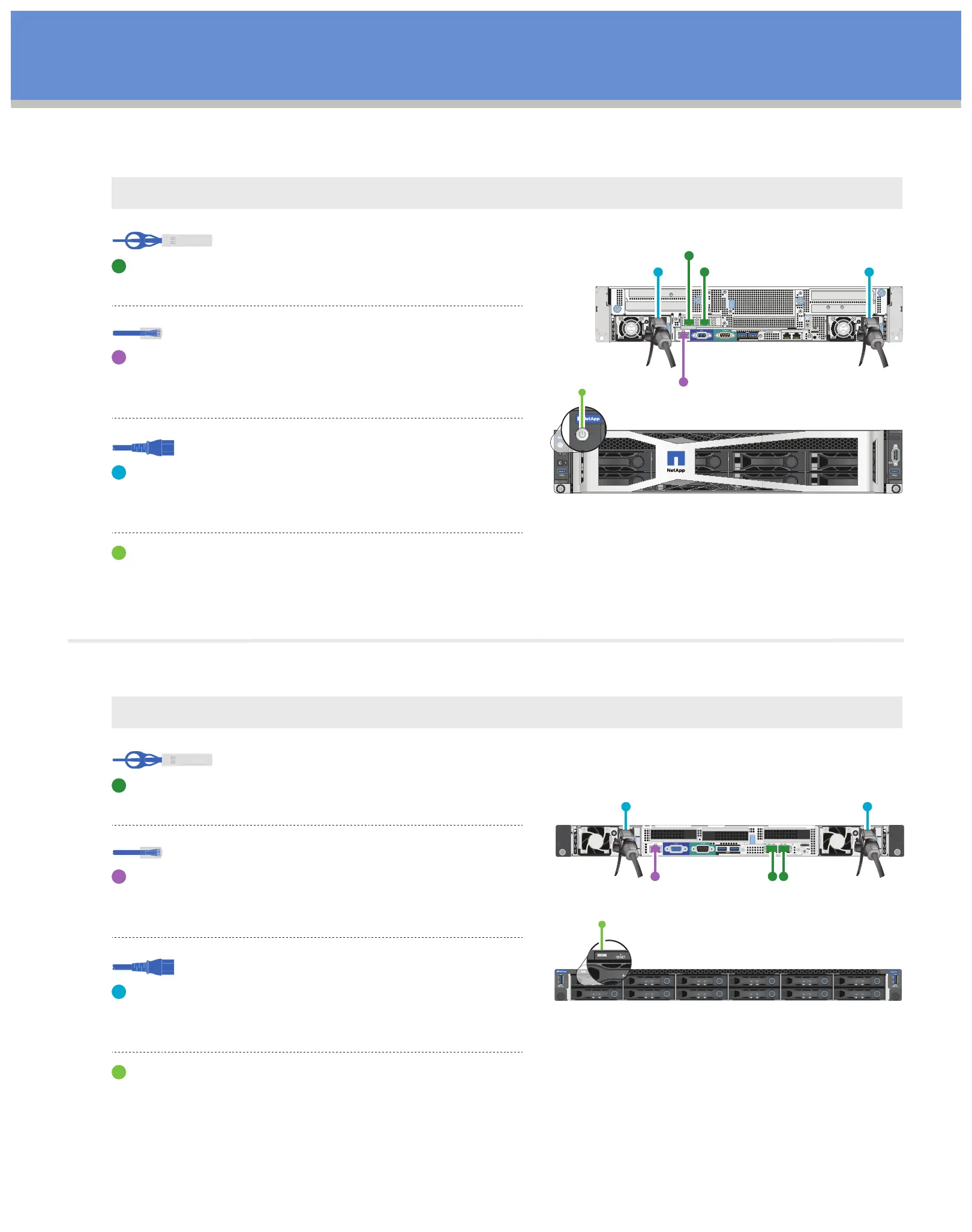
Cable the node | Stage 3 cont.
Note:
H610C nodes are deployed only in the two-cable configuration. Ensure that all the VLANs are present on ports C and D.
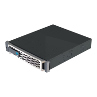
REAR
VIEW
PortC
PortD
IPMI
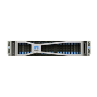
FRONT
VIEW
Connect the node to a 10/25GbE network using
two SFP28/SFP+ cables in ports C and D.
(Optional, recommended)
Connect the node to a 1GbE network using an
RJ45 connector in the IPMI port.
Connect both power cables to the node.
Plug the power cables to a 200‐240V
power outlet.
Press the power button at the front of the chassis.
Note: It takes approximately five minutes and 30 seconds
for the node to boot.
10/25GbE cables
H610C compute node
Power cables
1/10GbE cables
Note:
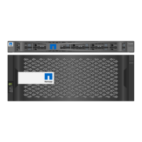
H615C nodes are deployed only in the two-cable configuration. Ensure that all the VLANs are present on ports A and B.
Connect the node to a 10/25GbE network using
two SFP28/SFP+ cables in ports A and B.
(Optional, recommended)
Connect the node to a 1GbE network using an
RJ45 connector in the IPMI port.
Connect both power cables to the node.
Plug the power cables to a 110-140V
power outlet.
Press the power button at the front of the chassis.
10/25GbE cables
H615C compute node
Power cables
1/10GbE cables
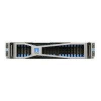
Port A Po
rt B
REAR
VIEW
IPMI
 Loading...