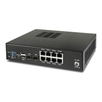
Product ManualXG-7100
// SWITCH-A
PORT 1 = ETH1
PORT 2 = ETH2
PORT 3 = ETH3
PORT 4 = ETH4
PORT 9 = UPLINK 1
PORT 10 = UPLINK 2
// SWITCH-B
PORT 5 = ETH5
PORT 6 = ETH6
PORT 7 = ETH7
PORT 8 = ETH8
SWITCH-A
ETH1-4 can talk to each other and to the LAGG uplink. PORT9-10 are members of this switch. . . this is required for
this switch to have uplink to pfSense.
SWITCH-B
ETH5-8 can talk to each other but because PORT9-10 are not included as members, clients connecting to ETH5-8 can
only talk to other clients on ETH5-8. They will not be able to reach the SoC where ix2 and ix3 are defined, so they
never reach pfSense. This can be useful if you want a device other than pfSense to act as the primary uplink for those
connected clients.
Since WAN and LAN are assigned to lagg0.4090 and lagg0.4091, if Port VLAN Mode is enabled, be sure to update
the LAN and WAN interface assignment to reference the appropriate VLAN. Also remember to create the new VLANs
with lagg0 as the parent interface.
If Port VLAN Mode is being used to handle untagged traffic, the LAGG0 interface should be added, enabled, and
configured under Interface Assignments.
2.4 Configuring the Switch
2.4.1 Switch Section
From the pfSense webGUI, there is a menu option called Switches under the Interfaces drop-down. This section
contains switch specific configuration options.
2.4. Configuring the Switch 8

 Loading...