NetworX NX Series Receiver Modules
Page 9
Enroll the Module
The following steps describe how to enroll and program the
module to be supervised by the NX-8.
1) With power applied and the system disarmed, enter [✻]
[8] at the keypad. The five function lights should start
flashing.
2) Enter the “Go To Program Code” (factory default is 9 7
1 3). The service light should flash and the five func-
tion lights should change from flashing to on steady.
3) Enter [0] [#], where [0] is the NX-8 control panel num-
ber and [#] is the entry key. The Armed LED should
turn on, indicating the control panel is waiting for a
programming location entry.
4) Enter [9] [1] [5] [#] to enroll the module for supervi-
sion. The keypad sounder should beep three times indi-
cating the NX-8 has accepted the enrolling request.
5) Exit program mode by entering [EXIT] [EXIT]. The
Service LED on the NX-8 turns on, indicating the con-
trol panel is enrolling the module. After about 12 sec-
onds, the service LED should turn off.
Program the Module
The following steps describe how to get the module into
program mode, load factory defaults if installing a new sys-
tem, and program transmitters into memory.
Programming Guidelines
■ When a transmitter is learned into memory, the module
claims a block of eight zones around that number (1-8,
9-16, 17-24, etc.). For example, learning a transmitter
into zone 13 automatically claims the zone block of 9
through 16. Only wireless transmitters can now be
assigned to these zones.
■ Do not learn wireless transmitters into a zone block
claimed by a hardwire expander or the panel.
■ If two modules are installed, they cannot share the
same zone block. For example, wireless transmitters
learned into zones 11 and 12 must reside in one mod-
ule.
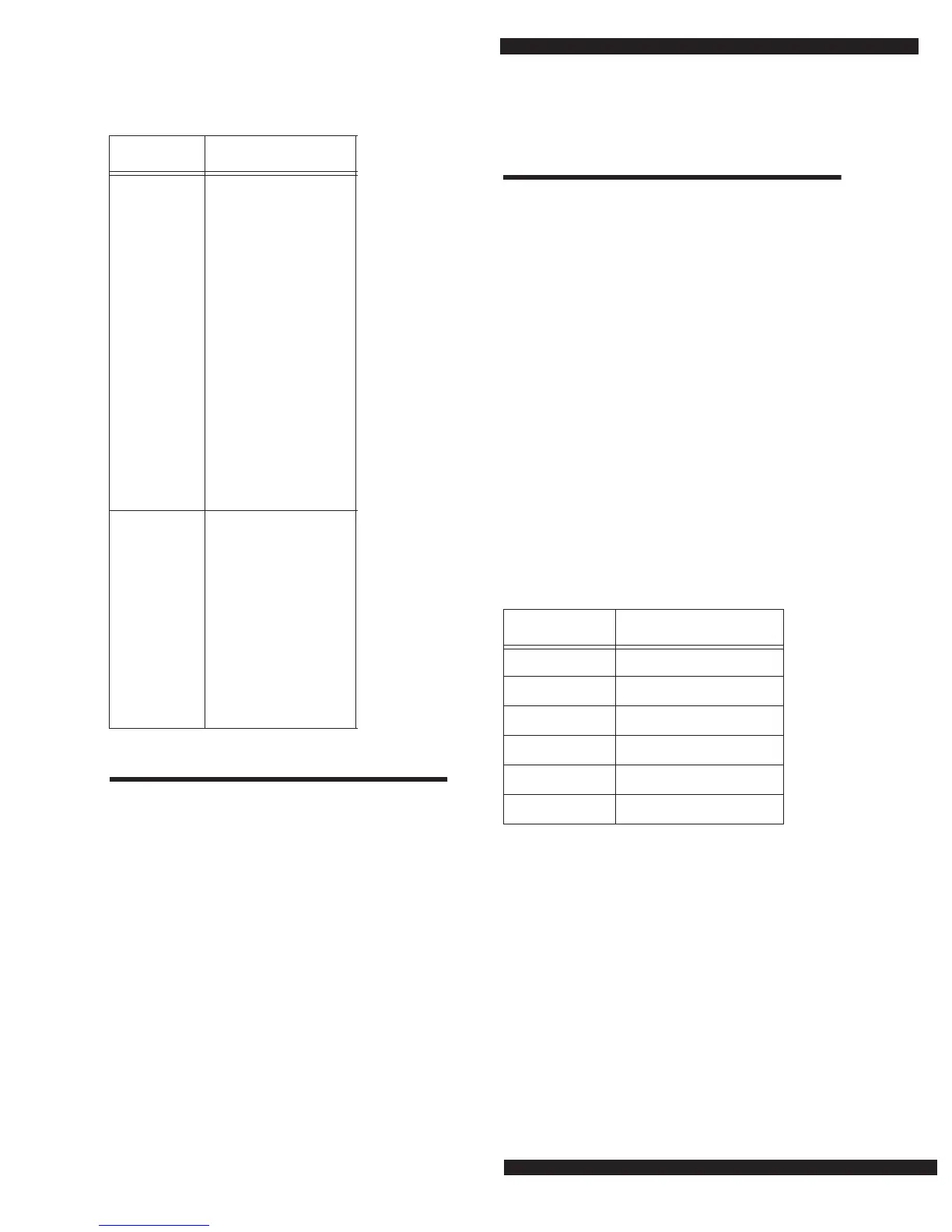
Fill in Table 4 to help keep track of zone block module
assignments. Be sure to circle the module type; RM =
receiver module, HE = hardwire expander, P = panel.
To program the module:
1) Enter [✻] [8] at the keypad. The five function lights
should start flashing.
2) Enter the “Go To Program Code” (factory default is 9 7
1 3). The service light should flash and the five func-
tion lights should change from flashing to on steady.
3) Enter [XX] [#], where [XX] is the DIP switch setting
module number and [#] is the entry key. The Armed
LED should turn on, indicating the control panel is
waiting for a programming location entry.
4) For new installations, enter [9] [1] [0] [#] to load fac-
tory defaults and clear any unwanted information in
memory before any further programming.
50 (All
default off)
1 - Keyfob user ID ❏
(off = all keyfobs
report as user 99;
on = keyfob reports
as its learned zone)
2 - Enable jam detect ❏
3 - Enable antenna
tamper (Only
selectable on Inter-
national versions,
reports as box
tamper) ❏
4 - Enable auto
advance to next
zone number ❏
5 - Enable partition 1
audible program-
ming beeps ❏
6-8 Not used
51 (Default
= 0)
Starting zone number
for receiver
0 = 1* (default) ❏
1 = 9 ❏
2 = 17 ❏
3 = 25 ❏
4 = 33 ❏
5 = 41 ❏
(* When set to 0, the
starting zone number
is determined by DIP
switch 3 setting.)
Table 3. Module Programming Worksheet Table
(cont.)
Location Segment 1 Segment 2
Table 4. Zone Block Module Assignments
Zone Block Assigned To Module
1 - 8 RM HE P #______
9 - 16 RM HE P #______
17 - 24 RM HE P #______
25 - 32 RM HE P #______
33 - 40 RM HE P #______
41 - 48 RM HE P #______
 Loading...