Connect the Current Transformers
Determine which mains wire feeds the breaker that you connected Neurio’s black wire to (Phase A). Trace
the line visually or use your multimeter to nd the wire. Remember that there may be voltage on the high
side of the main breaker.
Connect the Antenna
Connect the antenna cable to the antenna connector on your Neurio. Feed the other end of the antenna
cable through either the 0.5” or 0.75“ antenna mount. Use whichever size matches the knockouts in your
panel. Fasten the antenna cable onto the mount using the nut that is supplied on the cable. Then connect
your antenna to the antenna cable.
Check Your Work
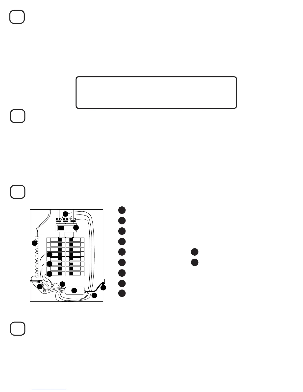
Now the panel should look something like this:
1 Mains Service Wires and 3 CTs, Connected to Ports #1, 2, and 3
5 Main Breaker
6 Neutral Bus Bar
7 Neurio
8 Voltage Cable
2 15A or 20A Single-pole Breaker on Phase A
3 15A or 20A Single-pole Breaker on Phase B
You should have three CTs on the mains, each with their labels facing away from the main breaker. The
voltage cable should be connected to 3 breakers on dierent phases and the neutral bus bar.
4 15A or 20A Single-pole Breaker on Phase C
11 Antenna and antenna mount
10 Antenna cable
5
6
7
Clip a CT around the mains wire you found. It should have its white labels facing away from the main
breaker. Plug this CT into port #1 on Neurio. Repeat this process for the red and blue wires. The CT on the
same phase as the red wire (Phase B) should connect to port #2, and the CT on the blue wire’s phase
(Phase C) should connect to port #3.
Find a 0.5” or 0.75” knockout that is within reach of your Neurio using the included antenna cable. Most
of the 0.5“ and 0.75” knockouts will have an inner knockout and an outer ring. For either size, you only
need to remove the inner knockout and should leave the outer ring in place. Use a screwdriver to remove
the inner knockout. Feed the antenna mount through the knockout until it clips into position. For more
detailed instructions and pictures, refer to Step 6 of the 2-Phase Installation Guide.
8
Close the Panel
Replace the cover on the panel and use the supplied Neurio breaker sticker to indicate which breaker
Neurio’s black, Phase A wire is connected to. Once the panel is closed and labelled, you can turn the main
breaker back on.
You’re almost done! Refer to the next section, Installation Validation, to make sure that Neurio is installed
correctly. After that, the homeowner just has to follow the Welcome Guide to connect their Neurio sensor to
their Neurio account.
9 3 Wire Taps (optional)
Make sure the three CTs are connected to ports #1, #2, and #3.
The CT on port #1 must be connected to Phase A.
The CT on port #2 must be connected to Phase B.
The CT on port #3 must be connected to Phase C.
 Loading...