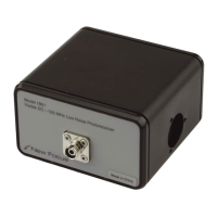
The New Focus Models 1801 and 1811 are 125-MHz, low-noise photoreceivers designed for RF photoreception. These devices are available in both DC and AC coupled versions, offering a typical bandwidth of 125 MHz and a current gain of 40 V/mA. They are suitable for a wide range of applications including wide bandwidth low-noise detection of signals distributed over fiber-optic cables, high-resolution spectroscopy, fiber-optic sensors, and optical metrology.
Function Description:
The photoreceivers are designed to convert optical signals into electrical signals with high gain and low noise. The Model 1801 incorporates a silicon/PIN photodiode, while the Model 1811 uses an InGaAs/PIN photodiode. In both models, the photodiode is followed by a low-noise transimpedance amplifier acting as a pre-amp, with a compensating amplifier as the output stage. This design allows for the use of a large-area diode while maintaining a large bandwidth with a flat response. The compensating amplifier increases the gain of the output stage with frequency, which leads to an increase in the noise floor starting at approximately 40 MHz, with a soft peak around 110 MHz. The entire package is shielded to eliminate RF pickup.
The AC-coupled versions include additional components: two blocking capacitors, a choke, and a DC bias monitor circuit. The high-pass filter on the AC-coupled output has a corner frequency of approximately 25 kHz, and the low-pass filter on the DC bias monitor output has a corner frequency of approximately 50 kHz.
Important Technical Specifications:
General:
- Bandwidth: Typical 125 MHz (DC-coupled and AC-coupled versions).
- Current Gain: 40 V/mA (AC-coupled), 1 V/mA (DC-coupled for 1801), 40 V/mA (DC-coupled for 1811).
- Risetime: 3 ns (typical).
- Output Impedance: 50 Ω.
- Power Requirements: ±15 V DC; 250 mA.
- RF Output: SMA connector.
- DC Bias Monitor Output (AC-coupled units only): SMB connector.
Model 1801 Specifics:
- Wavelength Range: 300-1050 nm.
- Minimum NEP:* 3.3 pW/√Hz (frequency dependent, see page 9 for details).
- CW Saturation Power: 120 μW @ 950 nm.
- Maximum Pulse Power: 5 mW.
- Detector Material/Type: Silicon/PIN.
- Detector Diameter: 0.8 mm.
- Optical Input: FC or free space (FS).
- Distance from window face to photodetector: 2.5 mm.
Model 1811 Specifics:
- Wavelength Range: 900-1700 nm.
- Minimum NEP:* 2.5 pW/√Hz (frequency dependent, see page 9 for details).
- CW Saturation Power: 120 μW @ 950 nm.
- Maximum Pulse Power: 5 mW.
- Detector Material/Type: InGaAs/PIN.
- Detector Diameter: 0.3 mm (FS), 0.1 mm (FC).
- Optical Input: FC or free space (FS).
- Distance from window face to photodetector: 0.5 mm.
Note: The equivalent input noise current at the peak (approx. 110 MHz) is greater than the low-frequency noise by a factor of 10.
Usage Features:
- Power Connection: The unit requires a ±15-V power supply providing a minimum of 0.25 A of current. New Focus recommends their Model 0901 power supply. Two power cables are provided: a Model 0921 banana plug-to-microconnector cable and a Model 0922 microconnector-to-microconnector cable. The Model 0922 cable should be used with the Model 0901 power supply's 0.3-A microconnector outputs. The Model 0921 cable is for power supplies other than the 0901.
- Optical Input:
- For free-space beam input, align the module so the beam is incident on the detector surface.
- For fiber-optic input, connect the fiber-optic cable from your optical source to the FC input connector on the front of the module. The detector is designed to receive an FC/PC connectorized fiber.
- To ensure operation in the linear region, keep input power levels well below the CW saturation power specification (which is wavelength dependent and inversely proportional to responsivity).
- Output Connection:
- If your RF measurement instrument has a male connector, connect it directly to the SMA female output connector (labeled "AC" on AC-coupled units) on the back of the module.
- If your instrument has a female connector, use an appropriate cable.
- On AC-coupled units, the DC bias can be monitored on the output labeled "DC" using the provided SMB-to-BNC cable.
Maintenance Features:
- Handling Precautions:
- Always ground yourself adequately before handling the photoreceiver or making connections to prevent electrostatic discharges, which can permanently damage the device. A ground strap is recommended.
- Ensure the optical connector is clean and undamaged before connecting it to the detector module.
- Warranty: New Focus, Inc. guarantees its products to be free of defects for one year from the date of shipment. This warranty covers defects but not incidental or consequential loss.
- Customer Service:
- Technical Support: Information and advice are available from applications engineers. For quickest response, provide the model and serial numbers of your product.
- Hours: 8:00–5:00 PST, Monday through Friday (excluding holidays).
- Toll Free: 1-866-NUFOCUS (1-866-683-6287) (from USA & Canada only).
- Phone: (408) 284-6808.
- Fax: (408) 980-8883.
- Email: techsupport@newfocus.com (responses typically within one business day).
- Service: In case of malfunction or damage, contact New Focus for a return authorization number and instructions for shipping the unit back for evaluation and repair.