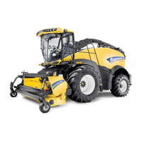
Do you have a question about the New Holland FR480 Forage Cruiser and is the answer not in the manual?
| Brand | New Holland |
|---|---|
| Model | FR480 Forage Cruiser |
| Category | Farm Equipment |
| Language | English |
Guidance on manual navigation, technical information system, and information unit search.
Details on using the manual, its sections, chapters, and information types.
Explanation of chapter identification, contents, and different types of technical information.
Details on information units, search methods, and page header/footer elements.
Important notices regarding equipment servicing, qualifications, and responsibilities.
Notes for the owner, and information on engine repair, FCR, and EST sources.
Environmental safety, operational hints, and battery recycling procedures.
Covers general safety rules, legal obligations, accident prevention, and hydraulic system safety.
Instructions for safe repair and maintenance operations, workshop practices, and personal safety.
Safety precautions for machine startup, hydraulics, fuel systems, wheels, and tire handling.
Guidance on personal safety, including warnings about heavy objects and pressurized systems.
Basic instructions for shop procedures, seal installation, and spare parts usage.
Practices for protecting electronic systems during charging/welding and the importance of special tools.
Minimum hardware tightening torques for normal assembly applications, in N m and lb ft.
Identification of hex cap screws, carriage bolts, nuts, and their property classes/grades.
Standard torque data for hydraulic connections, including general information, tolerance, and lubrication.
Torque values for metric O-Ring Boss port connections (ports and plugs).
Torque values for BSPP thread ports and metric face-seal ports, including different connector types.
Torque values for inch O-Ring Boss non-adjustable and adjustable port connections.
Torque values for inch ORB port plugs and metric four-bolt flange connections (Class 10.9 & 8.8).
Torque values for inch flange connections, tapered threads, and banjo bolt connections.
Torque values for O-Ring Face Seals (ORFS), JIC 37° flare, and 30° flare/60° cone connections.
Instructions for basic chain wear measurement, elongation, and causes of wear.
Table of wear limits for roller chains and specifications for new chain sizes.
Reference table for converting units of length, area, volume, mass, torque, power, pressure, temperature, flow, and speed.
List of operating alarms with descriptions, explanations, priority, activation, and resetting information.
Continuation of operating alarms, detailing specific fault codes and conditions.
Further operating alarms related to reel speed, calibration, and header adjustments.
More operating alarms covering drive, spout, and trailer system status.
Operating alarms related to module detection, communication loss, and IntelliFill™ system.
Further module communication alarms for LCP, ATCM, and CAN steer valve.
Details on system protection features, including automatic engine shutdown conditions.
Summary of alarms triggered by engine oil pressure, coolant temperature, and fuel temperature.
Continuation of timing tables for engine shutdown and derate values based on rail pressure and temperature.
Explanation of how to identify machine models and understand the serial number structure.
Diagram and notes defining machine orientations (front, rear, sides) relative to travel direction.
Alarms related to module detection, communication loss, and IntelliFill™ system status.
Further module communication alarms for LCP, ATCM, and CAN steer valve.
Timing information for engine shutdown, disengagement, and derate values based on alarm triggers.
Continuation of timing tables for engine shutdown and derate values based on rail pressure and temperature.
Explanation of how to identify machine models and understand the serial number structure.
Diagram and notes defining machine orientations (front, rear, sides) relative to travel direction.
Details for the engine and crankcase system, component 001.
Overview of engine service procedures, including removal and installation steps.
Safety precautions and steps for removing engine shielding before proceeding with removal.
Steps for removing rear shields and discharging the air-conditioning circuit.
Procedures for draining hydraulic oil and engine coolant, and disconnecting wiring harnesses.
Steps for disconnecting remaining wiring harnesses, ground cable, and starter motor lead.
Procedures for removing roof assembly components and sensors related to engine cooling and DEF.
Steps for disconnecting DEF/AdBlue® lines and couplers, and managing air intake tubes.
Procedures for supporting the roof assembly and removing associated hardware.
Steps to remove rear frame hardware and the complete roof assembly.
Instructions for removing air intake tubes and coolant outlet/inlet tubes.
Steps for removing remaining coolant tubes and breather tubes from the engine.
Procedures for removing the cooling fan, oil filter, support, and fan drive belt.
Steps for disconnecting hydraulic connectors and removing hydraulic hoses.
Instructions for removing various hoses and tubes connected to the engine.
Steps for removing hardware and covers from the rear frame and light assemblies.
Procedures for supporting the rear frame and engine, and disconnecting fuel/air lines.






 Loading...