Do you have a question about the Nexcom VTC 1031 Series and is the answer not in the manual?
Details product warranty period, return merchandise authorization process, and repair charges.
Covers essential safety info and recommendations for proper device installation.
Provides contact info for support and explains manual conventions for clarity.
Lists part numbers and ordering details for VTC 1031 and nROK 1031 series.
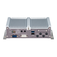
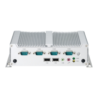
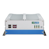
Illustrates front and rear views of the VTC 1031 model, highlighting external components.
Describes the VTC 1031 series capabilities, processor, and key features.
Details CPU, memory, video, storage, expansion, GNSS, LAN, and I/O specs for VTC models.
Provides detailed physical dimensions and layout diagrams for the VTC 1031 unit.
Diagrams showing numbered external connectors for easy identification on VTC and nROK models.
Explains the function and status indications of the power button and system LEDs.
Details pinouts for USB 2.0 ports and SIM card slots, essential for connectivity.
Describes pin assignments and LED status for PoE LAN1 and LAN2 ports on VTC 1031-C2.
Outlines essential safety guidelines and preparation steps before working with internal components.
Explains how to set 2-pin and 3-pin jumpers, including open and short configurations.
Provides comprehensive pinout definitions for various board-to-board connectors on the motherboard.
Details pin configurations for M.2 sockets used for LTE/5G NR modules and storage.
Step-by-step guide on how to remove the chassis cover for accessing internal components.
Instructions for mounting and connecting a 2.5" SATA hard drive into the system.
Guide on inserting M.2 WWAN modules (3042, 3050/3052) into the designated slot.
Instructions for properly inserting SO-DIMM memory modules into the socket.
Introduces the NEXCOM demo utility for testing and controlling I/O ports on VTC/nROK devices.
Explains settings for Power ON/OFF Delay Timer, RTC Wake Up Timer, and Watchdog Timer.
Details how to configure GPIO (GPO/GPI), Wake On LAN, External 12V, and Programmable LEDs.
Covers configuration for WWAN, SIM card, WiFi, Bluetooth, and GPS modules via software.
Introduces the u-blox NEO-M9N GNSS module, its capabilities, and features.
Lists key performance metrics for the GNSS receiver, including accuracy and sensitivity.
Describes GNSS tracking modes, security features, and supported interfaces/protocols.
Provides pinout details for the VIOB-GPS-06 module connectors (J2, J9).
Introduces the u-blox NEO-M9L GNSS module with 3D dead-reckoning capabilities.
Lists technical specifications for GPS with dead reckoning, including navigation rates and accuracy.
Details the pin assignments for the 26-pin male DB26 Multiport connector.
Explains how to connect external sources for digital inputs (Wet/Dry Contact).
Describes methods for connecting external devices for digital outputs (Wet/Dry Contact).
Introduces the multiport system, consisting of DB26 and output connectors.
Details the pin signals for the P1 connector (DB26 male) of the multiport cable.
Provides pin definitions for P2 (Pink) and P3 (Green) phone connectors.
Details pin assignments for the CN1, CN2, and CN3 connectors used for USB 2.0 data.
Explains how to configure power-on delay times via BIOS setup.
Details how to set power-off delay times through the BIOS interface.
Provides a general note on power consumption and suggests referring to the table.
Lists average and maximum current/wattage consumption for various device states and configurations.