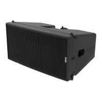
Page 28/90 GEO M12 HARDWARE SETUP PROCEDURE
- Rear connection of two subsequent modules is ensured by a link bar, with one safety point on a latch
and one quick release pin to adjust angle settings.
GEO M12 front rigging points GEO M12 rear rigging points GEO M12 angle settings
Angle splay setting sequences are as follow:
- GEO M1210 to GEO M1210: 0.25° (A) / 0.5° (B) / 1° (C) / 2° (D) / 3.5° (E) / 5° (F) / 7° (G) / 10° (H)
- GEO M1210 to GEO M1220: 10° (H) / 13° (I)
- GEO M1220 to GEO M1220: 13° (I) / 16° (J) / 20° (K)
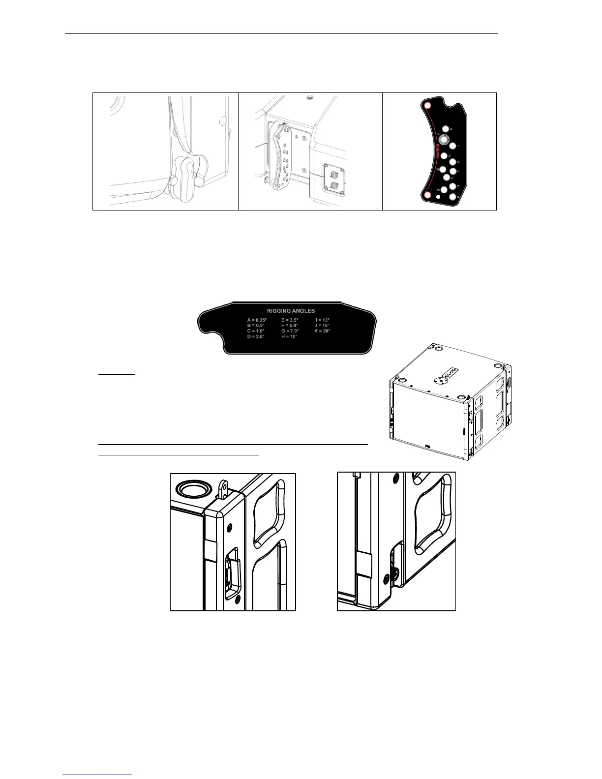
MSUB18 features a 4-points rigging system:
- Upper connection features retractable rigging links that can be
unlocked from the sides
- Lower connection features semi-auto lock rigging points that
lock with latches on the sides
Front and rear rigging points are identical so that MSUB15 count
be mounted reverse for cardioid setups
MSUB18 upper rigging points MSUB18 lower rigging points
Angle splay setting sequences are as follow:
- MSUB18 to MSUB18: 0°
- MSUB18 to GEO M1210 (or M1220): -12° / -9° / -6° / -3° / 0° / +3° / +6° / +9° / +12°
 Loading...