- Position second VNT-BUMPM12 on top of MSUB18
- Pull the bumper front latches, rotate the lower links so that connection points are double leg and
release the latches.
GEO M12 Left
- Pull the bumper front latches, rotate the upper links so that connection points are single leg and
release the latches.
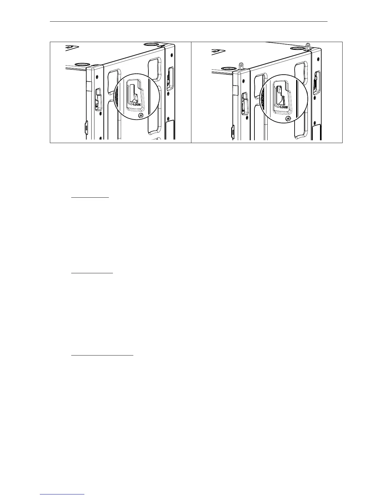
- Release first GEO M12 link bar, and set AutoRig
TM
in automatic lock position
- Position first GEO M12 on top of the bumper, front points will lock automatically
- Connect the bumper link bar (selection from -12° to +12° in 3° steps) to GEO M12 rear rigging plate
(hole marked “bumper”) Lock with the quick release pin BL0820.
GEO M12 Right
- Pull the bumper front latches, rotate the upper links so that connection points are double leg and
release the latches.
- Release first GEO M12 link bar.
- Position first GEO M12 on top of the bumper and lock it to the bumper with the 2 BL820 quick release
pins.
- Connect the bumper link bar (selection from -12° to +12° in 3° steps) to GEO M12 rear rigging plate
(hole marked “bumper”) Lock with the quick release pin BL0825.
Subsequent GEO M12s
- Position second GEO M12 cabinet with AutoRig
TM
in automatic lock position, and lock front points to
first GEO M12
- Unlock GEO M12 link bar
- Pull the latch to engage the guide in GEO M12 rear slot.
- Adjust the angle by inserting quick release pin BL820 in proper hole.
- Connect subsequent GEO M12 cabinets as with second.
 Loading...