PAGE 5/37
GENERAL SET-UP INSTRUCTIONS
ALPHA SERIES USER MANUAL V1.0
DATE: 14/01/00 18:27
General Set-up Instructions
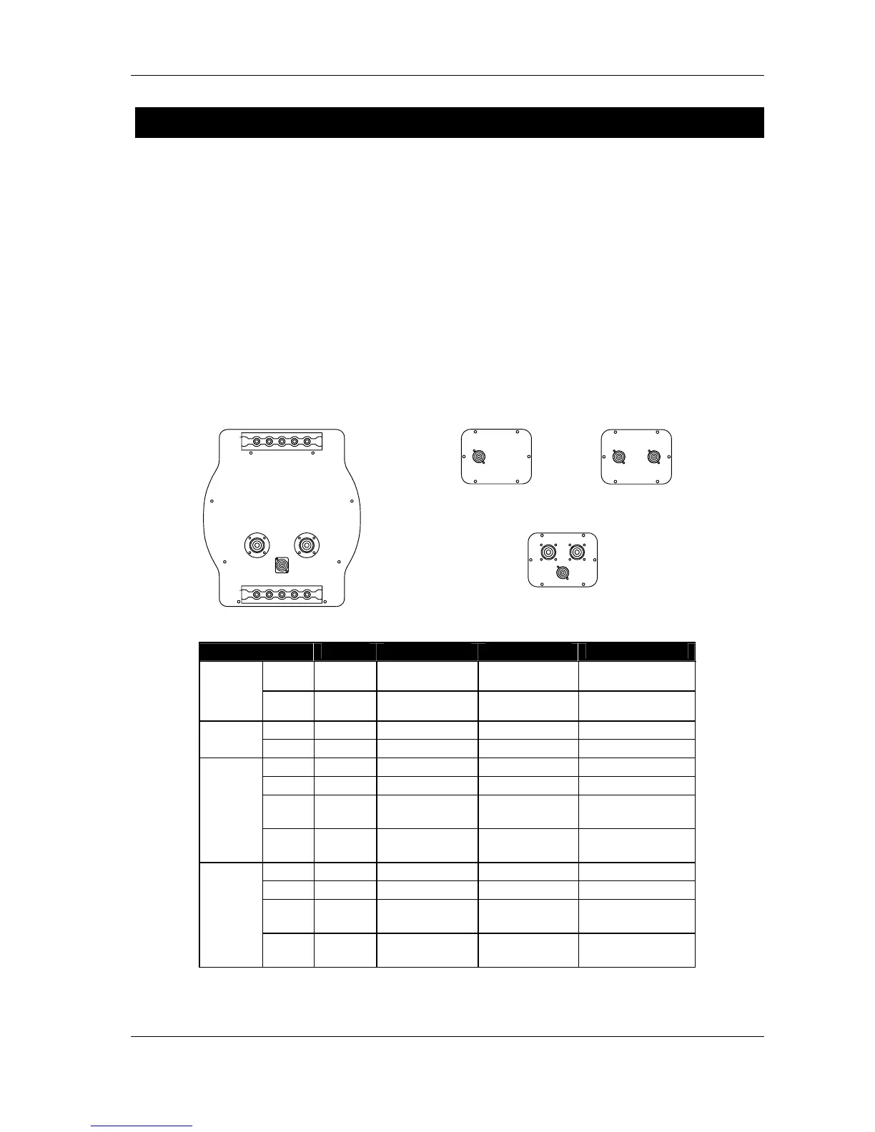
Speaker Wiring
Connectors
The loudspeakers are connected via SPEAKON connectors, NL4FC and NL8FC (not supplied). A
wiring diagram is printed on the connection panel located on the back of each cabinet. The pins of
the SPEAKON sockets are identified in/out and connected in parallel within the enclosures. A
single 8-conductor cable carries all four bands required by the Alpha M3/B1/S2 system and the
cabinet connectors allow all three types of cabinet to be safely linked at the loudspeaker end. (See
Connections Diagrams at the end of this manual).
NB: The Alpha S2 back panel features only one 4-pin SPEAKON connector in order to prevent
accidental parallel connection: very few amplifiers are able to drive such low impedance loads at
the required power level.
CONNECTOR
S2 B1-15 / B1-18 M3 / M8 EM / EF
1±
In / Out
VLF
To VLF (S2) To VLF (S2) To VLF (S2)
SP4
#1
2±
Not
connected
In / Out LF (B1) To LF (B1) To LF (B1)
1±
- To VLF (S2) - -
SP4
#2
2±
- In / Out LF (B1) -
1±
- - In VLF (S2) In / Out VLF (S2)
2±
- - In / Out LF (B1) In / Out LF (B1)
3±
- - In / Out MF
P: In / Out MF+HF
A: In / Out MF
SP8
#1
4±
- - In / Out HF
P: Not connected
A: In / Out HF
1±
- - In VLF (S2) In VLF (S2)
2±
- - In / Out LF (B1) In / Out LF (B1)
3±
- - In / Out MF
P: In / Out MF+HF
A: In / Out MF
SP8
#2
4±
- - In / Out HF
P: Not connected
A: In / Out HF
P = MF-HF passive / A = MF-HF active
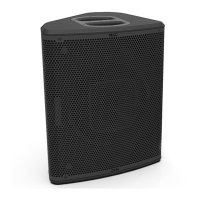
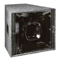
S2
B1/15
B1/18
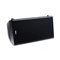
M3
M8
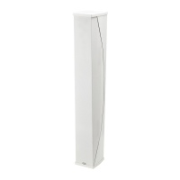
EM
EF
 Loading...