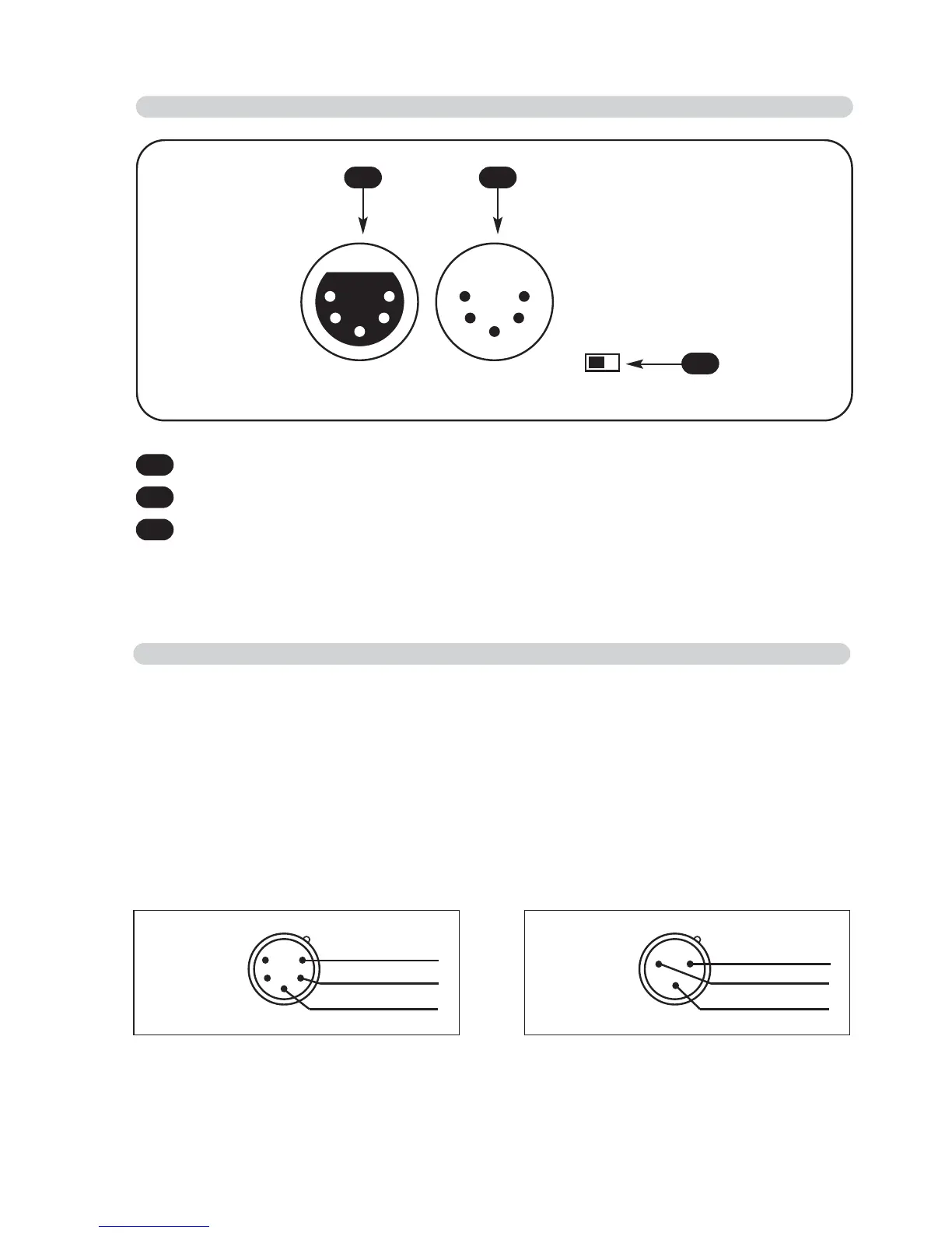
2.1 DESCRIPTION OF THE SIDE PANEL
1
Standard DMX 512 signal OUTPUT with a 3/5-pole cannon connector.
2
Standard DMX 512 signal INPUT with a 3/5-pole cannon connector.
3
DMX TERMINATOR
1 2
3
2.2
MAKING A DMX 512 SIGNAL CABLE
Wi DMX has a DMX 512 input/output that uses standard XLR 5-pin or XLR 3-pin
connectors.
The connection must be put into practice with shielded cable by these characteristics:
- 2 conductors + shield
- 120 Ohm impedance
- low capacity
- maximum transmission rate 250 Kbaud.
For the connection refer to the underlying picture
ATTENTION: the shield of the cable must never be connected to the ground of the
electrical system as this could cause faults during the working of the Wi DMX.
15
3
42
Common
DMX
-
DMX
+
XLR 5-pin
1
3
2
Common
DMX
-
DMX
+
XLR 3-pin