3> Before installing or uninstalling the SIM card, please power off the tracker.
3 Installation
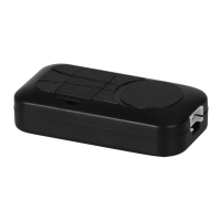
For CC-338, the tracker uses the 9-40V DC power supply, it is necessary connectin g to car battery all the
time, after the backup battery is full, the built in recharging circuit will stop rechar ging, and if the tracker is not
move, the tracker will go to power saving mode (GPS off, GPRS online), when the tracker begin to move, the
tracker will back to normal working mode.
The standard wire suit f or all the cars, the wire function descriptio n is as follow, if the car can be controlled
by OBD can bus, then use the OBD wire harness connect to the OBD s ocket is OK, it is easy and convenient.
RED or BROWN---- ------12V/24V car battery
BALCK------GND (Car Body)
WHITE -------ON Signal(Engine Running) Positive Input
Note: ON signal is used to indicator the engine is run ning (Positive means engine is running), if ON signal
is positive then the tracker wi
ll begin to upload location to server, if the ON signal is open the trac ker will stop to
upload location to server. If the GREEN wire is not connected to ON signal, the uploading will be controlled by
shock sensor, if the car begin to move the tra cker will begin to upload location to server, after the car stop
moving 2 minutes the tracker will stop to upload location to server.
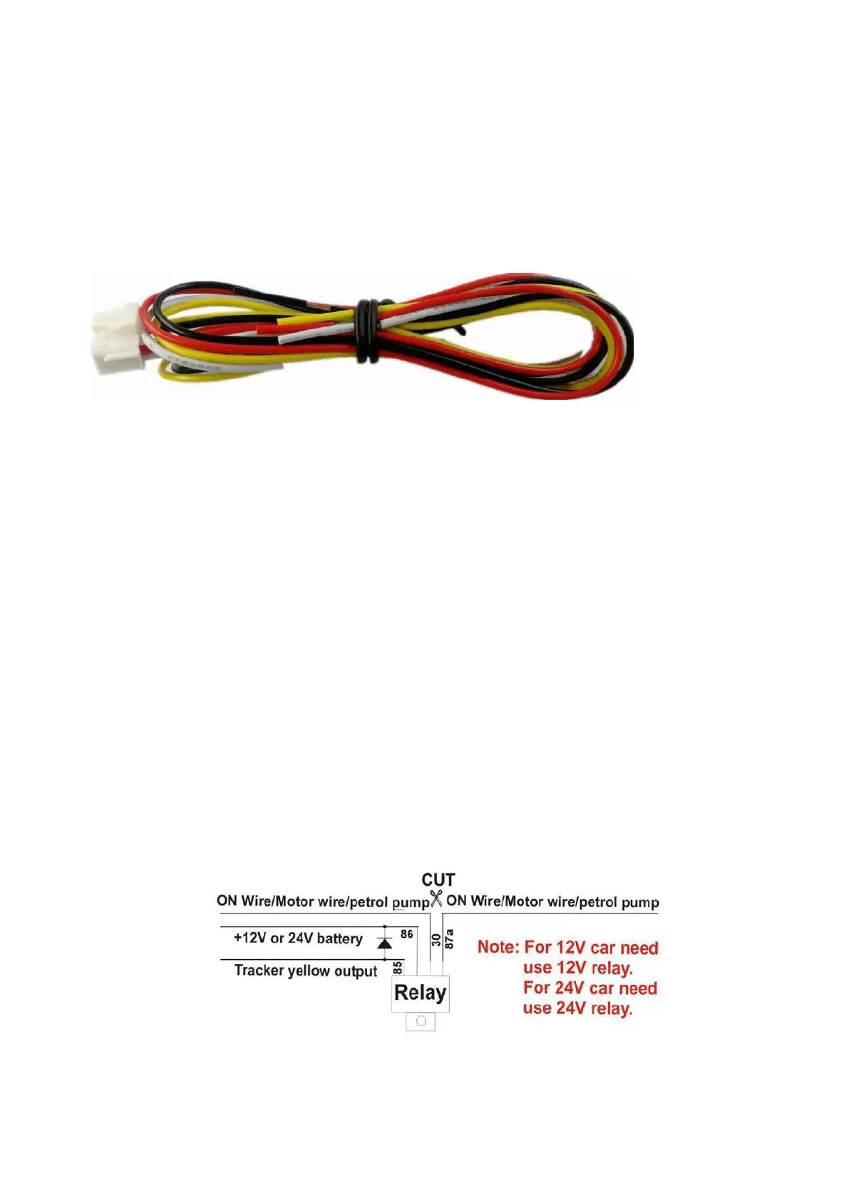
YELLOW----Turn off Engine Negative Output (Connect to Relay)
The engine cut command need add a rely to exec
ute, the tracker have a output engine cut wire, when the
tracker turn off the engine, this yellow wire will output a negative signal continuously, this wire can drive the
relay to control engine power supply or petrol pump power supply, then c an turn off the car engi ne. The output
current of the yellow wire is smaller than 500mA, and a diode is necessary to add to protect the tracker driving
wire, the diagram is as follow, Normally the turn off engine output used to control the car s
tarting motor or oil
pump motor line or ON wires.
 Loading...