10
Step 6: Using (12) #10 x ¾” THWS attach
both Base Plates to the base of the cabinet.
NOTE: The lift does not have a lower limit.
If the Cabinet is 8” taller than the lift column,
the lift may need to be blocked up.
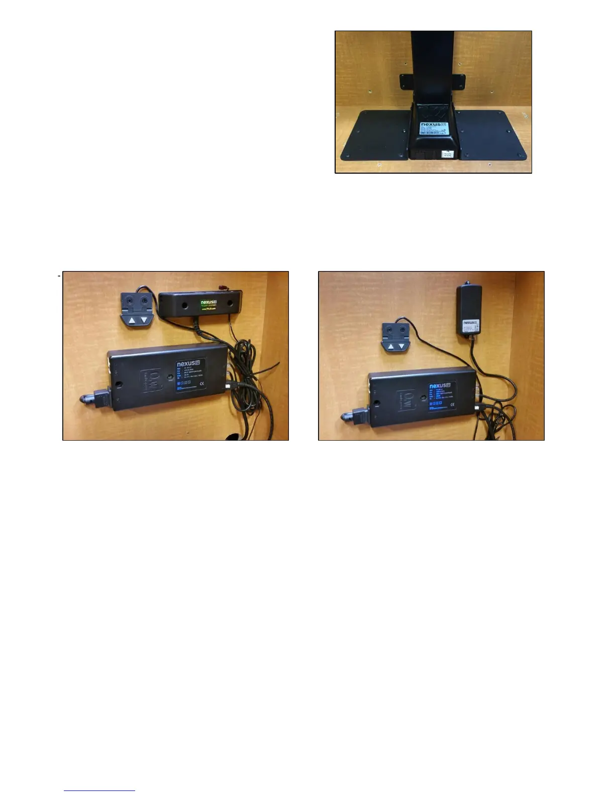
Step 7: Mount the Control Box and controls to the wall at a nearby accessible location: Using (2) #10 x 1 ¾”
FHWS mount the Control Box to the wall. Using (2) #8 x ¾” FHWS mount the Wired Back Up Switch. If you
ordered IR Controls, then you will use (2) #8 x ¾” FHWS to mount the IR Receiver. If you ordered RF Controls,
then you will use (2) #6 x ¾” FHWS to mount the RF Receiver.
Step 8: Connect the cables for IR Controls as noted on the diagram on the following page, or on page 12 for
RF Controls. Ensure that the motor cable is connected to port #1. The lift will not operate if motor the cable
is connected to ports #2 or #3.