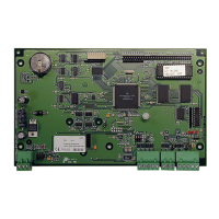
The provided document is an installation manual for the PW-3000 Intelligent Controller, part number PW3K1IC, manufactured by NexWatch. This device appears to be a core component of an access control or security system, designed for real-time processing of connected I/O interfaces, managing a database for the subsystem configuration and card holders, and maintaining an event log in battery-backed memory.
Function Description:
The PW-3000 Intelligent Controller serves as the central processing unit for a security system, handling real-time data from various input/output devices. It maintains a database of system configurations and cardholders, and logs events, ensuring continuous operation even during power outages thanks to its battery-backed memory. The controller supports multiple communication interfaces, including RS-232, RS-485, and Ethernet, allowing for flexible integration into different network environments and communication with various peripheral devices such as readers, alarms, and other controllers. It features on-board real-time clock maintenance for date and time, including adjustments for daylight savings. The system's program is stored in FLASH memory and can be downloaded through a serial port, enabling easy upgrades and changes to the board components.
Important Technical Specifications:
- Primary Power: 12 VDC ±10%, 400mA (550mA with PW3K1EN) (401mA with PW5K1M4). The controller accepts 12 VDC with an operating range of 10 to 16 VDC and consumes 400mA of current. A local power source is recommended, and connection to the board should be with minimum 18AWG wires. The addition of the PW3K1EN consumes an extra 150 mA of current, and the PW5K1M4 consumes less than 1 mA of extra current.
- Memory and Clock Backup: 3 V Lithium, type BR2325 battery. This battery ensures the retention of configuration data and the event buffer.
- Data Memory: 1MB standard (4MB with optional memory module, J3).
- Ports:
- Port 1 (J4,5,6): RS-232 or RS-485 (9,600 to 38,400 BPS, asynchronous)—optional Ethernet board RS-485 (9,600 to 38,400 BPS, asynchronous). Port 1 is a standard connection to the host computer. It can be configured as an RS-232 interface for direct connection or modem, or as an RS-485 interface for up to eight controller boards to share one host computer port.
- Port 2 & 3: RS-485. These interfaces allow multi-drop communication up to 4,000 feet (1,250 m shielded per port) using two twisted pairs (120Ω, 23pF minimum 24 AWG) with shield. The default speed for each port is 38.4Kbps but can be downgraded to 19.2Kbps or 9.6Kbps.
- Ethernet: When the Ethernet option board is present, the port is set to the RS-232 setting and DIP switch 5 must be ON (handshaking enabled), along with JP14 removed.
- Wire Requirements:
- RS-232/RS-485: 24 AWG, 1 twisted pair, 18 AWG, 4,000 ft (1,200m) max. For RS-485, a two-twisted pair (s) with shield (120Ω, 23pF, Belden 9842 or equivalent) is recommended.
- RS-232 24 AWG: 25 ft (7.5m) max.
- Alarm Input: 1 twisted pair, 30 ohms max.
- Environmental:
- Temperature: 0 to 49 °C, operating; -55 to +85 °C, storage.
- Humidity: 0 to 85% RHNC.
- DIP Switch Settings: The manual provides detailed DIP switch settings for various configurations, including hardware flow control for Port 1, baud rates (115.2K BPS, 9,600 BPS, 19,200 BPS, 38,400 BPS), and password login requirements.
- Jumper Settings: Jumpers are used to configure the controller hardware, including settings for RS-232/RS-485 on Port 1, Ethernet/COBOX Micro, and RS-485 EOL terminators for Ports 1, 2, and 3.
Usage Features:
- Communication Flexibility: The controller supports multiple communication protocols (RS-232, RS-485, Ethernet) to accommodate various system architectures and integration needs.
- Real-time Clock: An on-board real-time clock maintains accurate date and time, including automatic adjustments for daylight savings, which is crucial for event logging and scheduling.
- Firmware Updates: The program is stored in FLASH memory, allowing for easy updates and modifications via a serial port, ensuring the system can be adapted to new requirements or bug fixes.
- LED Operation: Three on-board LEDs (LED A, LED B, LED C) provide status information during power-up sequence and normal operation, indicating power-up complete, RAM/database testing, and activity on Host Port 1 and I/O Ports (2 & 3).
- Mounting Options: The board can be mounted on-edge in a rack-mount enclosure provided by NexWatch or it can be mounted flat against any surface using standoffs under the mounting holes provided in each of the four corners of the board. The functionality of this board does not change with the mounting selection.
- Alarm Inputs: The two alarm inputs on this board are dedicated to the detection of cabinet tamper and power fault monitoring. These are normally (non-alarm) closed contact inputs. If these inputs are not used, install a shorting wire between the signal terminal and the GND terminal to simulate the non-alarm state. The wiring between the alarm source and the input terminals is typically contained within one enclosure, and these inputs are not supervised.
Maintenance Features:
- Memory Backup Battery: A 3V Lithium battery (type BR2325) backs up the configuration data and the event buffer. This battery should be replaced annually or sooner if the cabinet is subjected to unusually high temperatures.
- Unpacking Procedure: Detailed instructions are provided for unpacking the equipment, including checking for shipping damage and verifying the contents against the packing list. Any damage or missing items should be reported immediately.
- Shipping Instructions: Clear instructions are given for shipping equipment back to NexWatch, including obtaining a Return Authorization Number (RMA), proper packaging, and marking the RMA number on all packages.
- Troubleshooting: The LED operation provides basic visual cues for troubleshooting power-up and communication issues.
- ESD Protection: The manual emphasizes the importance of handling ESD sensitive components in an approved static controlled workstation to prevent damage to CMOS integrated circuits and modules.
- Warnings and Cautions: The manual includes critical warnings regarding power supply connection, fire safety, and liability, emphasizing the need for qualified personnel to perform installation and maintenance, and adherence to local fire and safety codes. It also warns against connecting AC power to the socket until all wiring has been installed and rechecked.