Installation, Operating and Maintenance Instructions Installation, Operating and Maintenance Instructions
®®
2 3
Installation Instructions
1
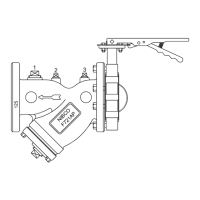
F721APLL, F721APLG, F721APSL and F721APSG with LD2000 Series Butterfly
Valves.
1. Ensure internal diameter of flanges, fittings, and pipe are compatible with the
butterfly valve for proper seal-face integrity and disc operation. See NIBCO Rubber
Lined Butterfly Valve IOM for additional details as necessary.
2. Ensure the mating pipeline flange faces are clean and undamaged, and the pipe
bores are clean and free from debris.
3. Close the valve completely to avoid possible damage.
Position the kit into the pipeline, taking care not damage the integrally molded seat
4. liner.
5. Insert the strainer flange gasket.
6. NIBCO LD2000 series butterfly valves have integral rubber faces that seal to the
attaching flange; therefore, a separate gasket is not necessary and should not be
used.
7. Carefully open the valve to assure free unobstructed disc movement.
8. After proper operation is verified, tighten all fasteners to the minimum
recommended torques listed below, using a crisscross pattern as shown in below in
Figure 1.
NOTE: Care shall be taken to prevent over tightening to prevent possible product
and property damage.
9. Cycle the valve to confirm unobstructed disc movement.
F721APNL and F721APNG with N200 Series Butterfly Valves.
1. Ensure internal diameter of flanges, fittings, and pipe are compatible with the
butterfly valve for proper seal-face integrity and disc operation. See NIBCO Rubber
Lined Butterfly Valve IOM for additional details as necessary.
2. Ensure the mating pipeline flange faces are clean and undamaged, and the pipe
bores are clean and free from debris.
3. Close the valve completely to avoid possible damage.
4. Position the kit into the pipeline, taking care not damage the cartridge seat liner.
Insert the strainer flange gasket. NIBCO N200 series butterfly valves have rubber
5. faces that seal to the attaching flange; therefore, a separate gasket is not necessary
and should not be used.
6. Carefully open the valve to assure free unobstructed disc movement.
7. The strainer-to-valve bolting will also need to be properly tightened.
8. The F721APNL and F721APNG kits are shipped with strainer-to-valve bolting in the
hand tight condition.
Installation Instructions Continued
F721APNL and F721APNG with N200 Series Butterfly Valves.
9. The cartridge style seat construction of the N200 series butterfly valve prohibits
complete tightening prior to installation in the piping system.
10. After proper operation is verified, tighten all fasteners to the minimum
recommended torques listed below, using a crisscross and cross-over pattern as
shown below.
10.1 It is critical that the cartridge liner be evenly compressed from both sides
ofthe mating flanges. (Refer to NIBCO Technical Bulletin - Installation Precautions
and Instructions for Large-Diameter Cartridge-Liner Butterfly Valves, NTB-1012-03
for additional details).
10.2 NIBCO recommends a multi-stepped process utilizing the crisscross and cross-over
pattern be used to draw the flanges against the liner from both side of the valve
at the same rate, ensuring the liner is compressed evenly. See Figure 2.
NOTE: Care shall be taken to prevent over tightening to prevent possible product
and property damage.
11. Cycle the valve to confirm unobstructed disc movement.
Maintenance
See NIBCO F721AP Strainer IOM for strainer maintenance.
See NIBCO Rubber Seated Butterfly Valve IOM for valve maintenance.
These documents, and more are available at NIBCO.com
Shipment and Storage
Butterfly valve discs are shipped in the nearly closed position to protect the sealing edge
and prevents the liner from taking a temporary set. The stem bushings and disc edge have
been coated with a factory-applied lubricant to prolong storage and service life.
The kits may be shipped or stored in any position, but care shall be taken to protect the
valve actuation hardware. Valves shall be stored indoors, and for a maximum of 10
years between a temperature range of 40˚ F to 90˚ F (4˚C to 32˚C).
2
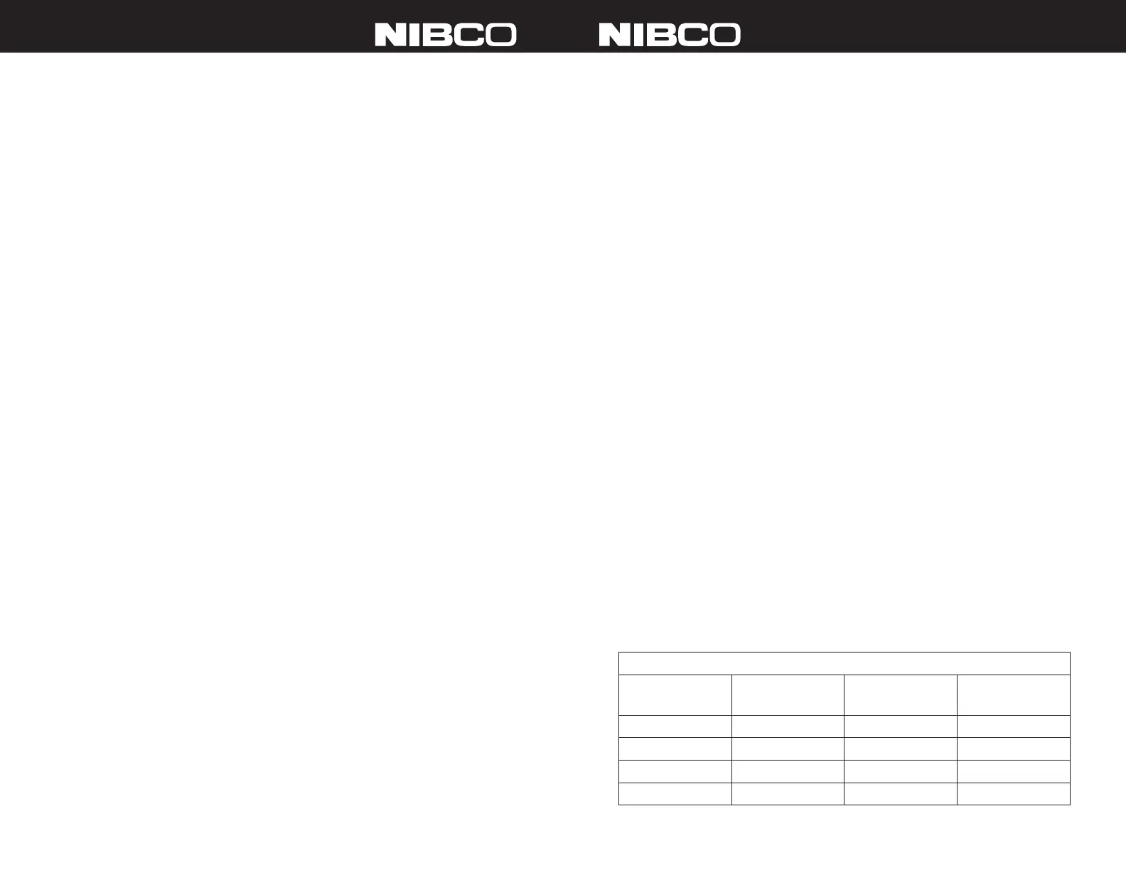
Recommended Fastener Tightening Torques
Flange Size Bolt Size Minimum Bolt
Torque (ft lbs)
Maximum Bolt
Torque (ft lbs)
2” to 4”
5
⁄8”
20 70
5” to 8”
¾”
30 120
10” and 12”
7
⁄8”
50 200
14” and 16”
1”
70 240
 Loading...