English
General
When a large number of electricity consumers are con-
nected to a property at the same time, there is a risk of
the main fuse tripping. CMS 10-200 is a current sensor
that is used to measure current at each incoming phase
conductor, ideally in the electrical distribution unit.
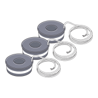
Contents
Current sensor3 x
Mounting
A current sensor can be installed on each incoming phase
conductor in to the electrical distribution unit to measure
the current. This is best done in the electrical distribution
unit.
Connect the current sensors to a multi-core cable in an
enclosure next to the distribution box. Use a multi-core
cable of at least 0,5 mm2 from the enclosure to the heat
pump.
The value for the size of the fuse is set in menu 5.1.12 to
match the size of the property’s main fuse. Here it is also
possible to adjust the current sensor’s transformer ratio.
CMS 10-200 has a transformer ratio of 1 250.
NOTE
The voltage to the input board must not exceed
3,2V, which is equivalent to 200A.
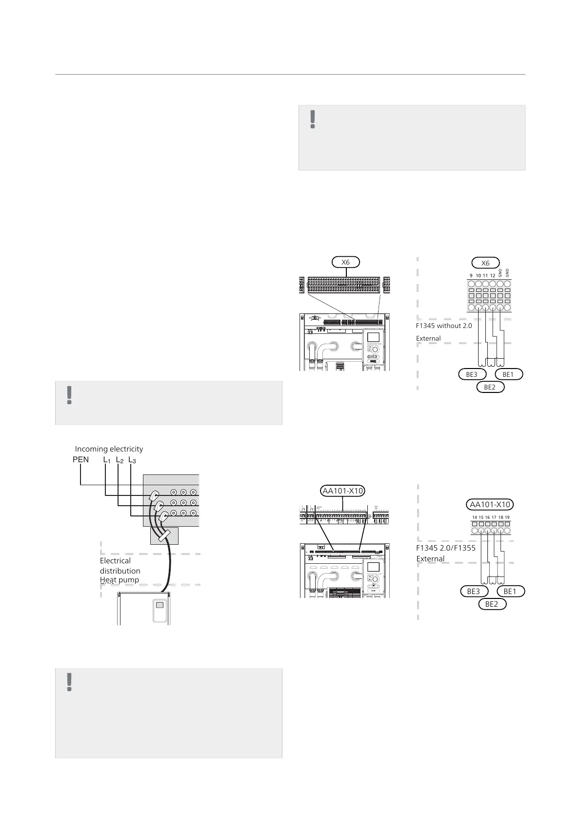
The image below is an example.
Electrical
distribution
unit
Incoming electricity
Heat pump
Electrical connection
NOTE
All electrical connections must be carried out
by an authorised electrician.
Electrical installation and wiring must be carried
out in accordance with the stipulations in force.
The main product must be disconnected from
the power supply when installing CMS 10-200.
NOTE
To prevent interference in the event of any spli-
cing, communication and/or sensor cables to
external connections must not be laid closer
than 20 cm from high voltage cables.
Connecting current sensor
F1345 without 2.0
Connect the cable to terminal block X6:10 to X6:11 and
X6:12 as well as to the common X6:GND terminal block
for the three current sensors.
F1345 utan 2.0
Externt
GND
GND
9 10 11 12
X6
External
F1345 without 2.0
BE3
BE2
BE1
F1345 with 2.0/F1355
Connect the cable to terminal block AA101-X10-X10:15
to AA101-X10-X10:16 and AA101-X10:17 as well as to
the common AA101-X10:18 terminal block for the three
current sensors.
F1345
Externt
14 15 16 17 18 19
External
F1345 2.0/F1355
BE3
BE2
BE1
AA101-X10
L1
-X3
-X4
1 2
3
-AA101 -AA101
N
L2
L3
1 2
3
4
5
6
7
8
9
-X5
1 2
3
4
5
6
7
8
9
-X6
-X7
-X8
-X9
-FC1
-AA101 -AA101
-AA101 -AA101 -AA101
1 2
3
4
1 2
3
1 2
3
1 2
3
4
5
-X10
A B A B
-AA3-X7
K1
-AA101
K2
K3
C C
NO
NC
K4
C
NO
NC
QN10 GP16
L
N
L L L
N N N
L
N
L
N
PE
PE
6
7
8
9 10
11 12
13
14
15
16
17
18
19 20
21 22
12V
A B
13
14
-BE1
-GP16
-BE2
-BE3
AUX 4
AUX 5
1 2
3
4
5
6
7
8
9 10
11 12
13
14
15
-AA3
-X6
0-10V
-EP14
-EP15
-BF1
16
17
18
2
-AA3
-X22
-AA3
-AA3
-X20
-X21
1
3
12
3
-X23
-BT1
-BT50
-BT25
-BT6
AUX 1
AUX 2
AUX 3
-BT7
-BT71
2.0
CMS 10-200 | GB4
 Loading...