Electrical connection
NOTE
All electrical connections must be carried out by
an authorised electrician.
Electrical installation and wiring must be carried
out in accordance with the stipulations in force.
F1145/F1245/F370/F470/F750 must not be
powered when installing RMU 40.
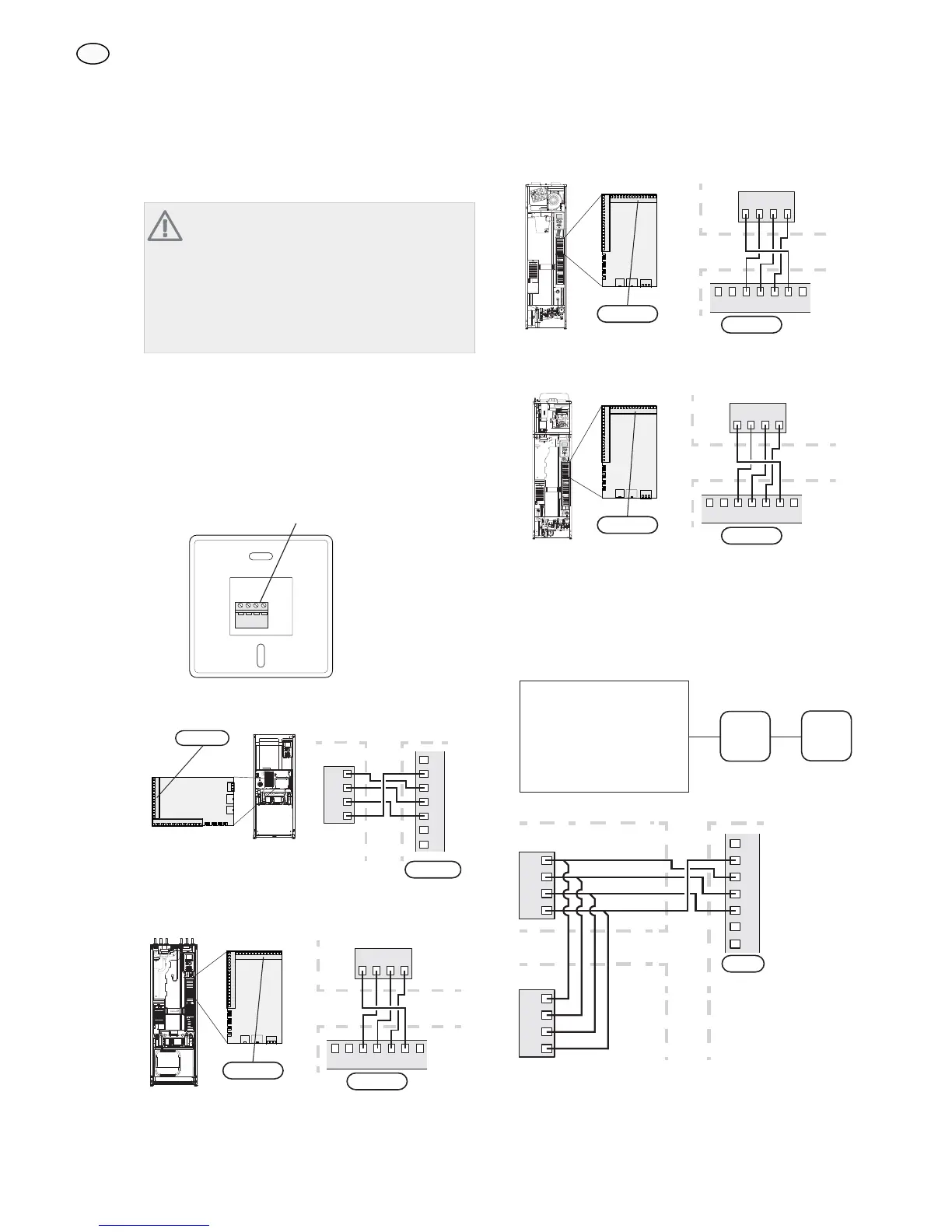
Connecting communication and power supp-
ly
The terminal block in RMU 40 is connected to terminal
block X4:9–12 on the input card (AA3) in the heat pump.
Use cable type LiYY, EKKX or similar.
RMU 40
+12V GND B A
7HUPLQDO EORFN
F1145
F1145RMU 40
A
B
GND
+12V
8
9
10
7
11
12
13
$$;
508b )
$$;
F1245
+12V
ABGND
12
1110 13987
F1245
RMU 40
508b
)
$$;
$$;
F370/F470
+12V
ABGND
12
1110 13987
F1245
RMU 40
508b
))
$$;
$$;
F750
+12V
ABGND
12
1110 13987
F1245
RMU 40
508b
)
$$;
LEK
$$;
Several RMU 40/SMS 40
If an additional RMU 40 or a SMS 40 is to be connected
to the F1145/F1245/F370/F470/F750 this should be con-
nected from the terminal block in the first unit. No more
than two units can be connected.
)))))
508b
606
508b
606
Värmepump
RMU 40
RMU 40
8
9
10
7
11
12
13
A
B
GND
+12V
A
B
GND
+12V
$$;
508b
508b
+HDW SXPS
GB