ENGLISH – 7
6. separate the item (E) by loosening the four screws (F)
m
The sleeves (G) on the gearmotor are suitable for
a spring support shaft with 48 mm diameter. If the
shutter shaft has a smaller diameter, replace the
sleeves with other sleeves having a 33 or 42 mm
diameter (not supplied) and place them against the
10 mm hole cut previously (see “Figure 5“).
F
E
G
9
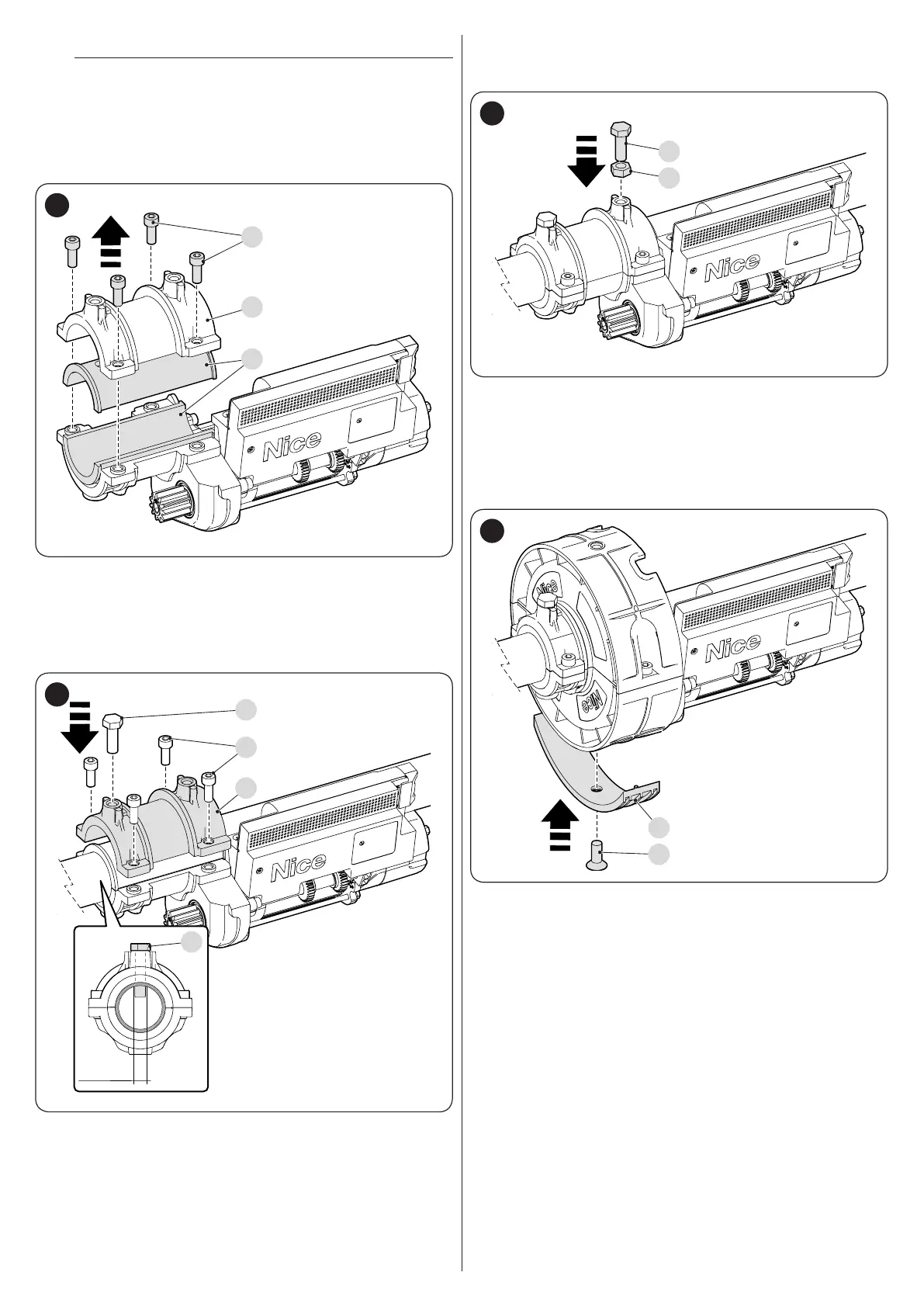
7. draw the gearmotor against the spring support shaft and
couple it with item (E) using the four screws (F) removed
previously
8. completely tighten the M10 screw supplied (H) without the
hexagonal nut, until it penetrates into the spring support
shaft through the 10 mm hole
Ø10 mm
F
E
H
H
10
9. tighten the M10 screw (J) with the nut supplied (K) to lock
the gearmotor on the spring support shaft; tighten the nut to
lock the screw in position
J
K
11
10. mount the roller band back on without bending it, as the
rollers could fall off
11. mount the two half-collars back on with the appropriate
screws
12. if there are any spring support boxes with a 220 mm diam-
eter, mount the adaptor supplied (L) using the appropriate
at-head screw (M)
L
M
12
13. cut a 12 mm hole on the last item of the shutter near the hole
on the half-collar (B)
14. fasten the last item of the shutter to the gearmotor using
screw (A) and the appropriate washer
 Loading...


