ENGLISH – 29
TERMINAL LEDS ON THE CONTROL UNIT
Status Meaning Possible solution
OP LED
OFF Everything normal Open input not active.
On Intervention of Open input
It is normal if one of the devices connected to the Open input is
active.
CL LED
OFF Everything normal Open input not active.
On Intervention of Close input
It is normal if one of the devices connected to the Close input is
active.
FCA LED
OFF Intervention of the limit switch The boom is in the opening position.
On No intervention of the limit switch The boom is in a position other than the opening position.
FCC LED
OFF Intervention of the limit switch The boom is in the closing position.
On No intervention of the limit switch The boom is in a position other than the closing position.
FURTHER INFORMATION
(Accessories)
9
10 FURTHER DETAILS (Accessories)
9.1 CONNECTING AN SM-TYPE RADIO RECEIVER
The control unit has a slot for mounting radio receivers with SM
connector (optional accessories) belonging to the SMXI, OXI, etc.
families, which can be used to remotely control the control unit
through transmitters that intervene on the unit’s inputs.
f
Before installing a receiver, disconnect the power
supply to the control unit.
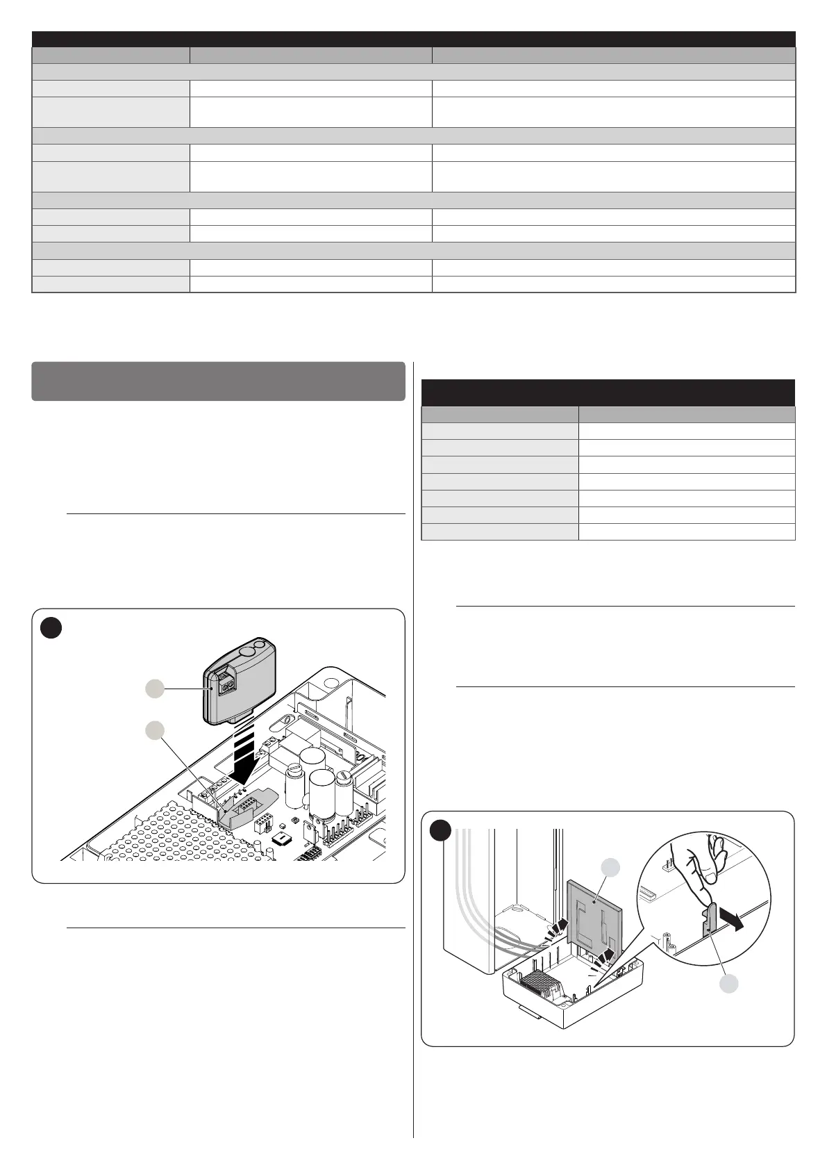
To install a receiver ("Figure 47"):
1. insert the receiver (A) in the appropriate slot (B) on the con-
trol unit’s electronic board.
A
B
47
The association between the radio receiver output and the control
performed by the motor is shown in "Table 12":
l
For further information, consult the specic manual
of the receiver.
Table 12
SMXI / SMXIS OR OXI / OXIFM / OXIT / OXITFM IN MODE 1 OR
MODE 2
Receiver output Command
Output No. 1 "Step-by-Step"
Output No. 2 "Stop"
Output No. 3 “Open”
Output No. 4 “Close”
Output No. 5 Courtesy light
Output No. 6 Radio channel 1
Output No. 7 Radio channel 2
9.2 CONNECTING AND INSTALLING THE BACK-
UP BATTERY
f
The electrical connection of the battery to the con-
trol unit must be made only after completing all the
installation and programming stages, as the battery
is an emergency power supply.
f
Before installing a back-up battery, disconnect the
power supply to the control unit.
To install and connect the battery:
1. unhook the control unit box from its position
2. open the box
3. access the battery compartment by releasing the catch (A)
and lifting the part (B)
A
B
48