There are 4 terminals on the DT1 board, of these 2 are power inputs, 1 is the key
switch input and 1 is the alarm input. The use of each terminal is described below.
+12 The positive input for the power supply (11.5 to 14V D.C.).
GND The negative (ground) input for the power supply.
K/S The key switch input. This input is driven in the same manner as the alarm
input below. When active, the key switch input puts the DT1 into “Away/On”
mode [the default setting requires +5 to 15V DC on K/S for “Away/On” mode].
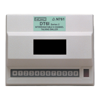
CH1 This is the alarm input. The input is held low via an internal pull down resistor to
GND. The input can be put into its alarm state by either applying voltage to it or
removing voltage from it, depending upon the configuration of the input’s
polarity (for further information on input polarity refer to the ALARM INPUT
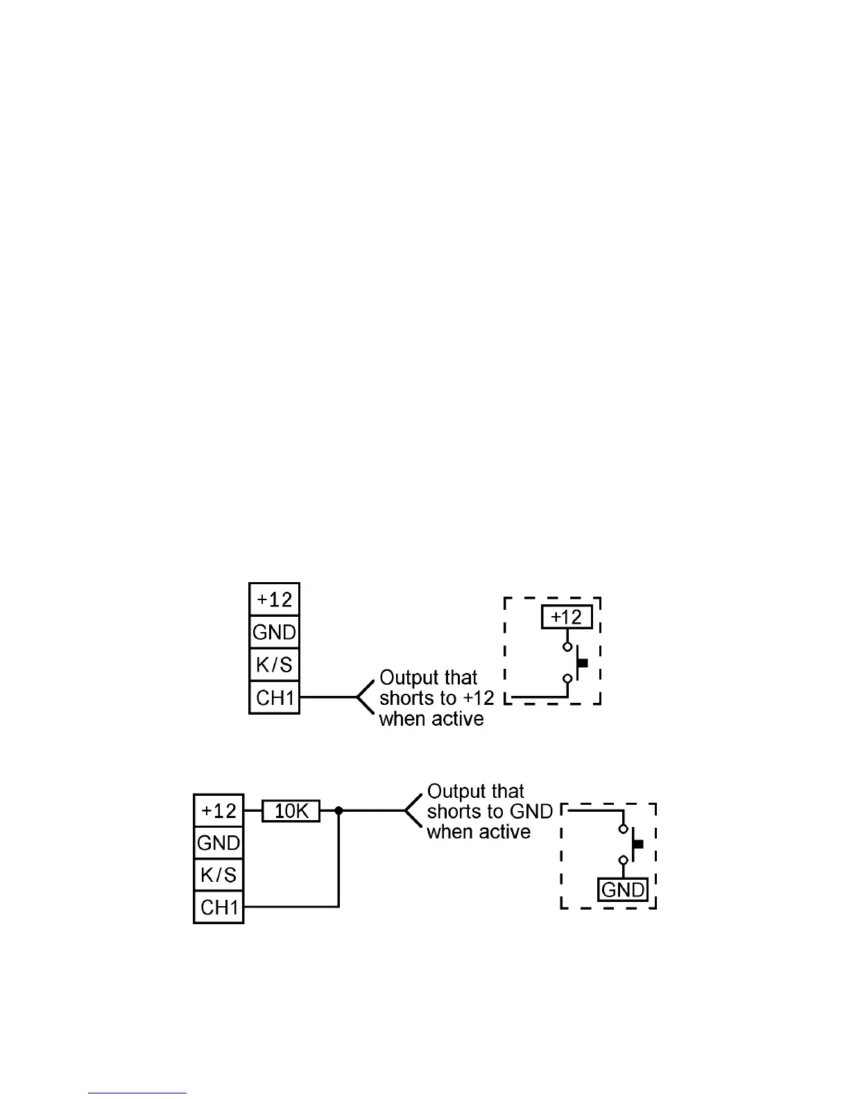
POLARITY section on page 10). To trigger the input from a source that only
drives low (eg. an Open Collector output or a normally open switch to GND) the
input will have to be pulled up to the positive voltage rail via a 10K resistor as
shown in Figure 3 below [the default setting requires +5 to 15V DC on CH1 to
trigger the dialler].
Figure 2: Connecting an output that drives high to the DT1.
Figure 3: Connecting an output that drives low to the DT1.
 Loading...