Troubleshooting
6-100 Manual # 42-02-7223 C1
ICE-IEQ Earthquake Board
The Earthquake board provides an interface between motion sensing devices and the iControl
elevator controller.
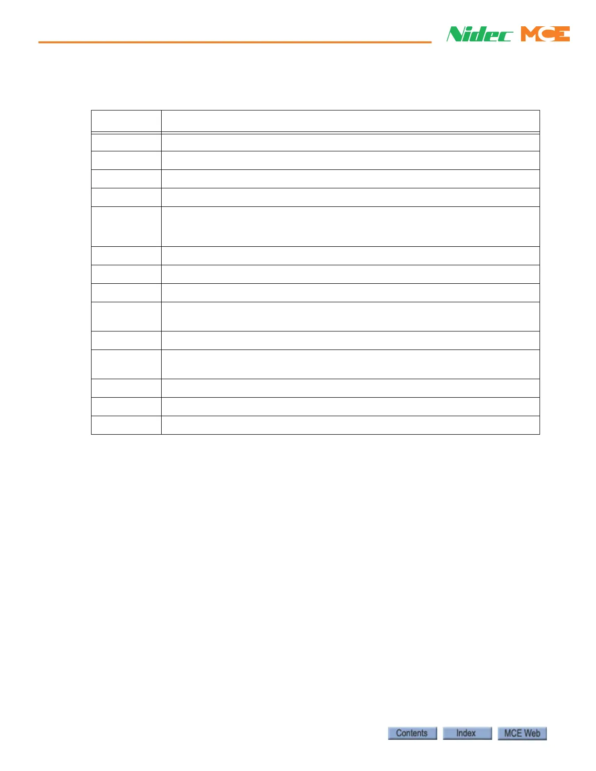
Table 6.7 IFIELD-MODULE-L Terminals on the ICE-FM Board (Brake Module)
Terminal Description
1 1 BUS: AC input supply to the ICE-FML Board.
2 2B BUS: AC input supply to the ICE-FML Board.
FMO+ Field Module Output, positive, to brake coil.
FMO- Field Module Output, negative, to brake coil.
FMSI Field Module Safety Input: Jumpered to FMSO. FMSI and FMSO are always jum-
pered together unless there is a requirement for a mechanical safety contact to
break between the load and the field module.
FMS0 Field Module Safety Output: Jumpered to FMSI. (see FMSI)
FMS1 Field Module Snubber 1: When used as a Brake Module, a shunt RC parallel net-
work (RB & CB) is connected between FMS1 and FMLD.
FMS2 Field Module Snubber 2: N/C
FMLD Field Module Load Diode: FMLD is connected to the cathode of a diode on the ICE-
FM board. FMLD is also connected to RC network RB & CB (see FMS1).
DTP Factory Use Only
FMX1 AC power input to Field Module from brake contacts (70 VAC min, 300 VAC max)
FMX2 AC power input to Field Module from brake contacts (70 VAC min, 300 VAC max)