iControl Circuit Board Quick References
Manual # 42-02-7223 C1 6-101
6
iControl DC
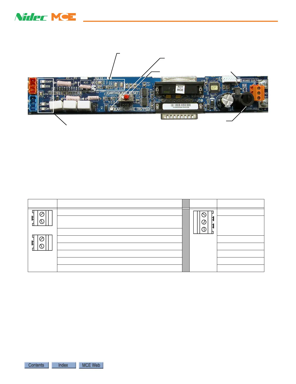
Figure 6.6 ICE-IEQ Earthquake Board
Table 6.8 Earthquake Board Connections
Connector Signal Connector Signal
EQSP 1:Spare. 0V=Normal. 120VAC=Tripped
1: Common
ESS: 120VAC= Normal, 0V= Tripped
(120VAC from #2 bus, through sensor to ESS)
CWX2: 18VAC
CWX1: 18VAC
CW2: 24VDC= Normal, 0V= String shorted
CW1: 24VDC= Normal, 0V= String shorted
EQSP LED
On = EQ fault
Off = No EQ fault
ESS LED
On = Normal
Off = Seismic device tripped
+24VDC Test point
CW2 LED, On = CW String OK
CW1 LED, On = CW String OK
EQ Board Reset
On = EQ sensor tripped
Fuse FCW
1/4A, 250V, MDQ
Tes t po i nts
GND,
+5V,
+3.3V
Board Query LED