Troubleshooting
6-144 Manual # 42-02-7223 C1
1. Remove the semiconductor fuses and the ribbon cable from J2 on the SCR-LGA board.
2. Disconnect the wires attached to terminals 2 and 3 on SCR1 through 6 in the drive.
3. Remove the three mounting screws on top of the SCR-SN board and remove the board.
Transfer the angle brackets (35-30-0009) to the new board. Lightly tighten the screws.
4. Install the new SCR-SN board and install the mounting screws (19-01-0012) and flat
washer (19-04-0004). Torque the mounting screws to 15-20 inch pounds.
5. Connect the wires as indicated below. Torque the M6 machine screws to 40-48 inch
pounds. Ensure that the ring lug does not cross the outer limits of the bus bar. To ensure
proper clearance, the space between bus bars A and B must be maintained.
• Note: The terminal number is on the top left side of the SCR pack near the terminal.
• Wire from E1 to SCR1 terminal 2
• Wire from E3 to SCR2 terminal 2
• Wire from E5 to SCR3 terminal 2
• Wire from E7 to SCR4 terminal 3
• Wire from E9 to SCR5 terminal 2
• Wire from E11 to SCR6 terminal 2
• Wire from E2 to SCR1 terminal 3
• Wire from E4 to SCR2 terminal 3
• Wire from E6 to SCR3 terminal 3
• Wire from E8 to SCR4 terminal 2
• Wire from E10 to SCR5 terminal 3
• Wire from E12 to SCR6 terminal 3
6. Install the semiconductor fuses (see Replacing the Semiconductor Fuses) and tighten
the screws that attach the copper bracket to the SCR-SN board.
7. Reinstall the swing tray that holds the SCR-LGA and SCR-PS board.
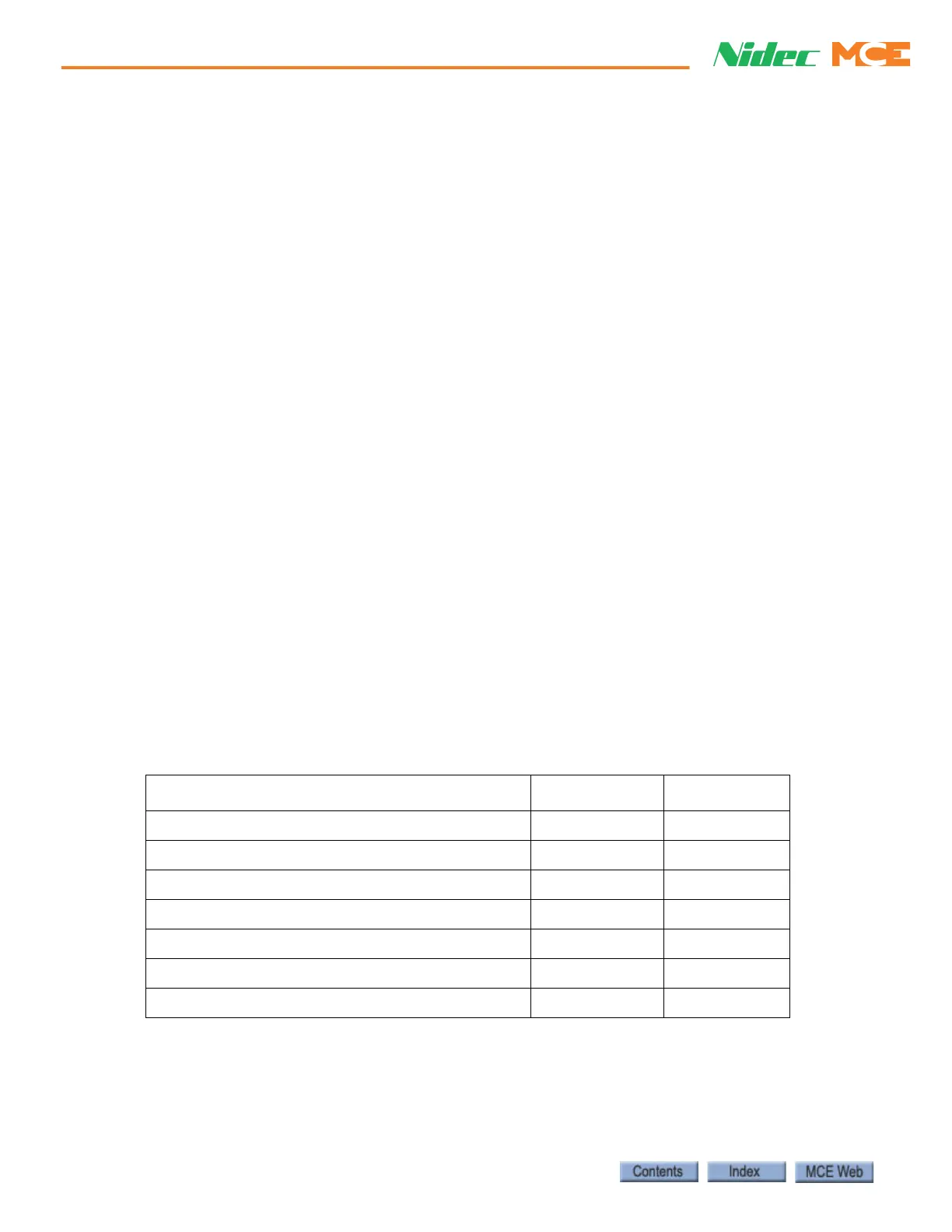
Table 6.35 Replacement Parts for SCR-SN
ITEM (DESCRIPTION) MCE PART # UNIT
SCR-SN (SCR Drive Snubber Board) SCR-SN Each
Insulator (Insulator for the SCR-SN board) 41-06-0017 Each
M6 Mach. Screw (M6 x 16MM Mach. Screw) 35-74-A5FT Set (30 EA.)
Kep Screw (8-32 x 3/8” Kep Screw) 19-01-0012 Each
Flat Washer (#8 Flat Washer) 19-04-0004 Each
Kep Nut (8-32 Kep Nut) 19-02-0005 Each
Angle Bracket (Copper Angle Bracket Bus Bar) 35-30-0009 Each
 Loading...