Troubleshooting
6-146 Manual # 42-02-7223 C1
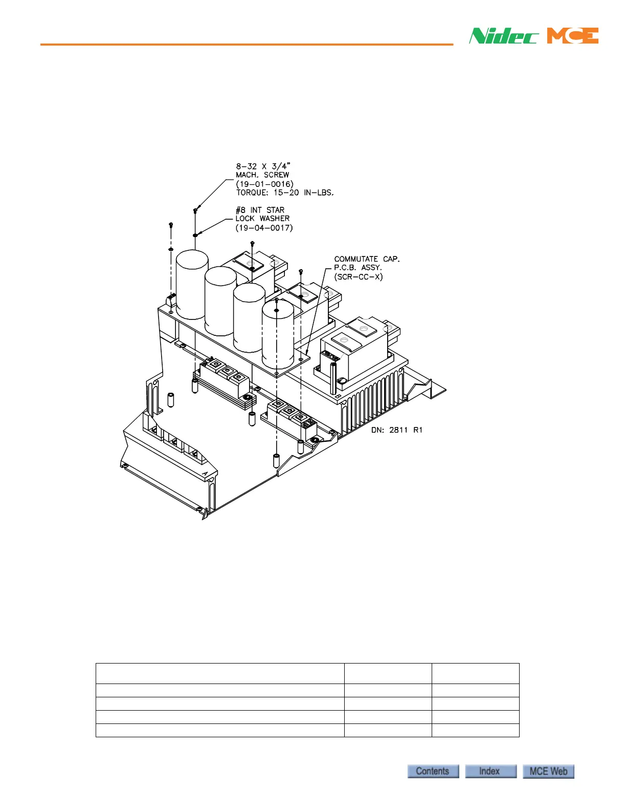
Replacing the SCR-CC H/L Board To gain access to the SCR-CC-H/L board, the
SCR-DS board must be removed. Label the wires you disconnect so they can be reconnected
correctly. The three studs (X1, A, AX) on the board should be torqued with care.
Figure 6.33 Replacing the SCR-CC H/L Board
1. Label and disconnect the wires on the studs (X1, A, AK) and J1 of the SCR-CC-H/L
board.
2. Remove the mounting screws and the board.
3. Install the new SCR-CC board and torque the mounting screws to 15-20 inch pounds.
4. Install all the wires that connect to J1.
5. Reconnect the wires to the studs (X1, A, AK). Torque the nuts to 22-30 inch pounds.
6. Reinstall the SCR-DS board.
Table 6.37 Replacement Parts for SCR-CC
ITEM (DESCRIPTION) MCE PART # UNIT
SCR-CC-L (commutation Board Low Voltage) SCR-CC-L Each
SCR-CC-H (Commutation Board High Voltage) SCR-CC-H Each
Mach. Screw (8-32 x 3/4” Mach. Screw) 19-01-0016 Each
Star Lock Washer (#8 Star Lock Washer) 19-01-0017 Each
 Loading...