Using iView
8-28 Manual # 42-02-7223 C1
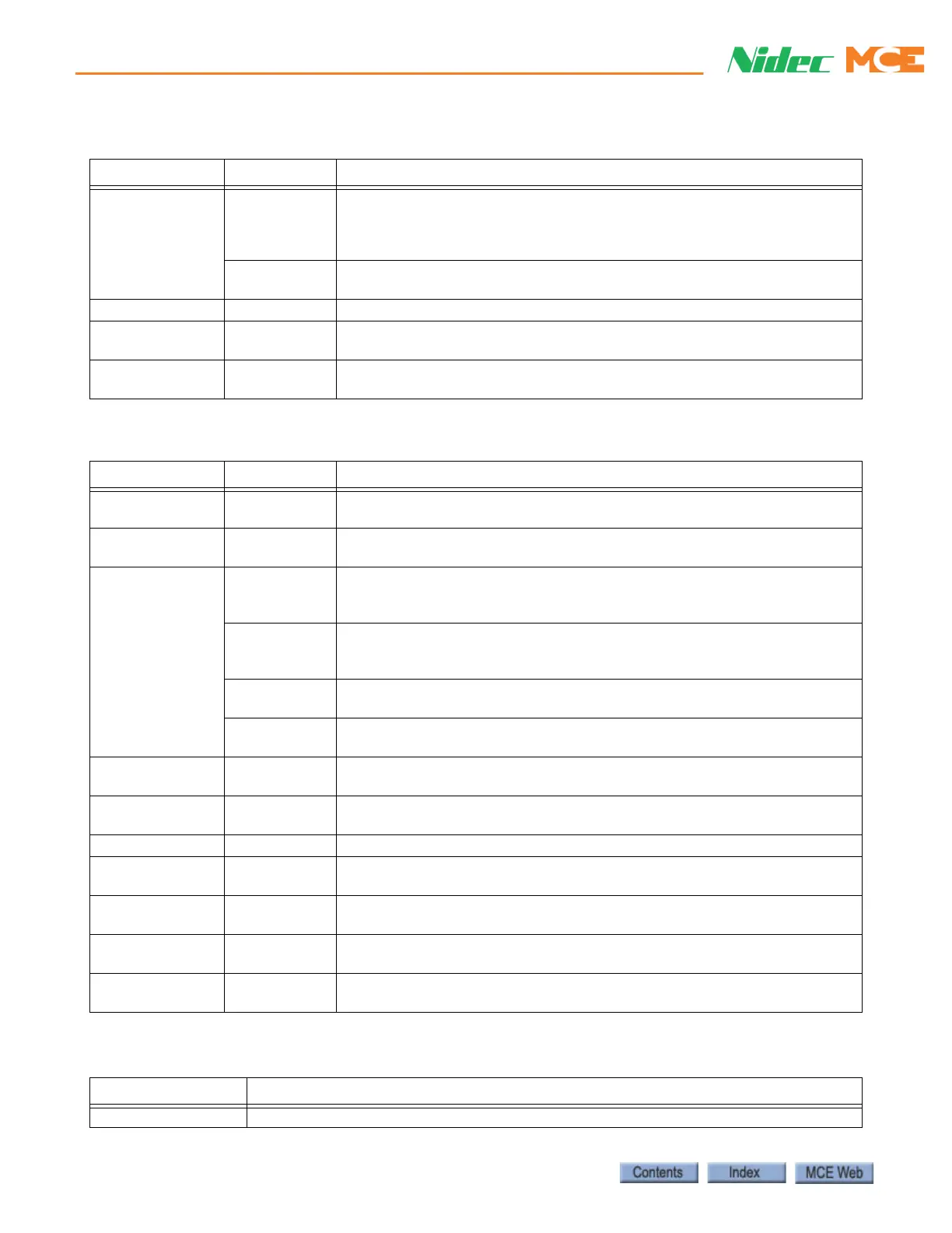
Pattern Common Display and edit parameters common to all pattern profiles. Position
encoder resolution, leveling and releveling speeds, pattern scaling, dead
zone distance, door pre-opening distance, and position synchronization by
floor or terminal switches.
Modes Parameter settings for Standard, Earthquake, Emergency power, Emer-
gency slowdown, Correction, Inspection, and Alternate 1-2 profiles.
Security Configure car call inputs active and car call security enables
Terminal
Switches
Position margin settings for up and down normal terminal and emergency
terminal switches, and Overspeed 1 margin setting.
Timer Tables Programming of timed operations (Sabbath, Swing and Auto stop opera-
tion).
Table 8.6 Controller - Diagnostics Tabs
Tab Sub-Tab Content
Car Statistics Displays Odometer, Power Cycles, Motion Cycles, Door Cycles, Number of
runs and relevels.
Data Trap Use this tool to record and analyze controller data including input and out-
put states, internal flags and parameter values.
Diagnostic
Flags
Car Operation Displays status of car operation input and output flags, including front and
rear doors, e.g. car call above, car call below. Click arrow buttons to dis-
play dependent outputs.
Motion Displays the status of Passenger (automatic) and Inspection mode motion
related inputs and outputs, e.g. Ready, Synchronization and Qualifier sta-
tus.
Drive Displays the status of Drive related inputs and outputs, e.g. Up direction
request, Pattern enable, and Motor run mode.
Safety Displays the status of Safety related inputs and outputs, e.g. Car top exit
open, Governor open, and Safety (Car) open.
Diagnostic
Outputs
Selection and display of up to sixteen system outputs for monitoring or
diagnosis. Hundreds of outputs are available.
Enhanced
Diagnostics
Selection and display of diagnostic messages used by MCE technical sup-
port.
Event Log Display of recorded controller events.
Fault Bypass Enable/disable selected system faults to facilitate adjustment and testing.
Display of faults currently bypassed.
Terminal
Switches Status
Displays the learned terminal switch speeds and positions, overspeed and
position fault thresholds and last pass positions and speeds.
Virtual
Oscilloscope
An on-board oscilloscope with software selection of test point signals to
be monitored and customizable display.
Call Generator Use this dialog to generate a new call list (script) or execute an existing
script.
Table 8.7 Controller - Setup Tabs
Tab Content
Brake Calibrate the brake voltage settings (see page 2-38).
Table 8.5 Controller - Configuration Tabs
Tab Sub-Tab Content
 Loading...