Niko A/S • Stenager 5 • DK-6400 Sønderborg • tel +45 7442 4726 • info@niko.dk • www.niko.dk (46)
4Y75X_4-76X_4-78X_03_R3_24034TVA_GB
User manual / GB
Use
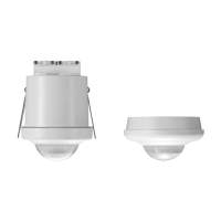
The 360° DALI master detector consists of a single unit containing a control
unit for DALI devices in up to three daylight zones with dimming as a
function of incident daylight and up to two secondary zones for On/Off or
dimming depending on the configuration.
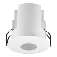
The detector is designed for indoor installation and has a built-in light sensor
and IR receiver for use in offices, schools and government buildings. The
detector is suitable for both large and small areas.
The detector has a built-in relay for controlling either lighting or ventilation.
Communication on the DALI bus follows the DALI addressable principle,
EN/IEC 62386-0/02.
A maximum of 64 DALI Control Gear can be connected to the detector. A
push-button power switch is connected directly to the detector.
The detector has a built-in DALI power supply, which must not be
connected to the external DALI power supply, nor may several master
detectors be connected in parallel, as this will destroy both the DALI ballasts
and the detector.
The detector can be integrated into solutions with DALI system components
for overriding zones, either with DALI potentiometers, Niko-Servodan
PMU-DALI, type 74-597 or DALI switch, Niko-Servodan DCP-4/BI, type
70-020. The 360 ° detection range can be divided into three sectors, A – B
– C, each covering 20°. Sensitivity can be adjusted either collectively for all
sectors or individually for each sector. Sectors can be isolated completely.
Fig.2
Programming and changes to settings are performed by IR remote control
type 4-934 (accessory) or by the Niko Sensor Tool app and belonging IR-
dongle type 4-936 (accessory). Simple overrides can be performed using
the IR user remote (4-935, accessory), such as on/off and dimming, either
for all zones at the same time or for each zone individually.
Typenr.
41-750
41-751
41-760
41-761
41-780
41-781
41-784
41-785
Flush mounted Fig. 3
• • • •
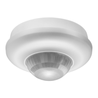
Surface mounted Fig. 4
• • • •
Ceiling height 2-3,4 m
• • • •
High ceiling 4-8 m
• • • •
Wireless EnOcean
• • • •
Secondary detector 4-752/753
• • • •
Secondary detector 4-762/763
• • • •
Guideline
The following guideline can be used for quick detector setup:
. Position the detector. Fig. 1.
2. Connect the detector according to the circuit diagram. The detector is
now in the “Out-of-the-box” mode. Fig. 8.
3. Test the installation for any errors or missing luminaires.
4. Initialise all DALI devices and divide the luminaires into zones. Fig. 1.1.
Note: Now the detector operates according to factory settings
If this is required - go directly to step 3
For other settings continue with step 5-3
5. Select mode. Fig. 2.1.
6. Program the required function: Automatic On/Off or Active On/Off
with automatic off via the detector for the individual zones. Fig. 3.2.
7. Select the number of daylight zones, 2 or 3. Fig. 1.2.
8. Choose whether the daylight zones are to remain at the minimum level
or if they are to turn off in case of over illumination. Fig. 9.1.
9. Set the required lux level for the daylight zones. Fig. 4.1.
0. Set the maximum lux output for the lighting system. See documentation
for the lighting system or measure with a lux meter. Fig. 4.7.
. Configure times. Fig. 7/Fig. 5.1-5.4.
2. The detector makes a fine-calibration of the lux-setting based on the
room reflectance, when the lux level is 00 lux and nobody is in the
room (typically at night). It may in certain cases be necessary to fine
tune using a lux meter. Fig. 4.15. This can only be performed after the
detector has performed fine-calibration. Fig. 10.2.
3. Enable a “Burn-in”. Applies to fluorescent tube lights only. Fig. 9.3.
Installation
Location:
The detector responds to movement and heat in relation to the
surroundings. Avoid placing the detector close to heat sources such as
cookers, electric radiators or ventilation systems, or moving objects such as
hanging mobiles etc. This may cause unintended activation. Fig. 1.
Detector DALI, Master,
41-750, 41-751, 41-760, 41-761, 41-780,
41-781, 41-784 and 41-785
Valid for software version 9 - See versionsno.