Do you have a question about the Nikon AF-S DX Nikkor ED 55-200/4-5.6G and is the answer not in the manual?
| Brand | Nikon |
|---|---|
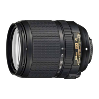
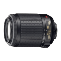
| Model | AF-S DX Nikkor ED 55-200/4-5.6G |
| Category | Camera Lens |
| Language | English |
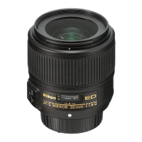
Details about the lens construction, mount, and compatibility.
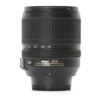
Specifies the zoom range of the lens.
Indicates the widest aperture available at different focal lengths.
Details the optical elements and groups within the lens.
Specifies the field of view.
Lists the marked focal lengths on the lens.
How distance data is outputted to the camera.
Mechanism for operating the zoom ring.
Autofocus mechanism and manual focus operation.
Minimum focusing distance of the lens.
Describes the automatic diaphragm control.
Available aperture values at different focal lengths.
Method used for exposure measurement.
Filter thread size for accessories.
Physical size of the lens.
Mass of the lens.
Important precautions before starting disassembly procedures.
Guidelines for working with lead-free solder products.
Steps to remove the rear cover ring from the lens.
Instructions for mounting the 4th lens group onto the 3rd lens group.
Steps to assemble the straight tube unit with the 3rd lens group.
Installing adjusting washer, collars, and screws for the 1st lens group.
Assembling the focus ring and 1st lens-G sliding ring.
Securing the assembled lens body components.
Attaching friction cloth and inserting friction spring.
Assembling focus gear ring with mid-lens barrel unit.
Securing the focus gear ring with a stopper screw.
Installing zoom coupling plates into the mid-lens barrel unit.
Handling and components of MR sensor unit and focus brush.
Diagram showing the self-made tool for waveform inspection.
Step-by-step guide for inspecting and adjusting the MR encoder output.
Using the FILTER function to reduce waveform noise.
Addressing low amplitude by checking MR head or sensor unit.
Addressing amplitude drops related to focus gear ring unit.
Attaching the AF contact unit to the lens body.
Assembling and adhering zoom ring and reinforcement ring.
Installing the zoom ring unit into the lens body.
Adjusting the zoom brush position.
Notes on handling SWM unit and grease application.
Steps for fixing the main PCB and connecting FPCs.
Attaching holders and preparing alignment equipment.
Steps to create the center positioning tool.
Preparing cardboards for alignment charts and viewers.
Connecting cables for the alignment equipment.
Setting up equipment for shooting alignment charts.
Steps to center the lens holder on the alignment equipment.
Mounting the lens and connecting video/fiber cables.
Adjusting brightness and lens shape for pinhole image.
Checking and adjusting pinhole shape on monitor.
Using alignment screwdrivers to loosen lens chamber screws.
Rotating micrometers to achieve target shape.
Tightening screws, locking holder, and removing lens.
Preparing camera and setting up the alignment chart.
Turning on the viewers for chart illumination.
Fitting lens and adjusting viewfinder alignment.
Connecting PC and starting adjustment software.
Selecting lens and resetting logs in the software.
Adjusting focus ring and observing 2nd lens group.
Detailed steps for rough periphery adjustment of lens.
Setting focus mode and adjusting tripod position.
Clicking the measurement button in the software.
Sliding tripod for repeated measurements.
Addressing warning messages related to brightness or quality mode.
Pointing cursor to confirmation screen and clicking.
Making periphery adjustments based on displayed results.
Using reference points for inserting adjustment screw.
Purpose of the positioning tool for lens alignment.
List of required parts for creating the tool.
Initial steps for assembling the lens holder tool.
Rotating and fixing the rear cover ring with glue.
Reinforcing the bayonet mount and cover ring with adhesive.
Attaching the mount rotation stopper screw.
Purpose of the setting board for chart illumination.
Materials needed and preparation steps.
Detailed steps for creating the setting board.
Methods to prevent viewers from falling off.
Adjusting washer thickness for focus movement.
Adjusting washer thickness for back focus.
Mounting a tool to check the aperture diameter.
Adjusting aperture lever position if out of standard.
Attaching rubber ring and light-shielding plate.
Securing the rear cover ring with screws.
List of adjustments for main PCB, SWM, or MR encoder.
List of necessary equipment and tools for inspection.
Requirements for the inspection and adjustment program.
Diagram showing the system setup for inspection and adjustment.
Step-by-step guide to adjust MR duty.
Notes on waveform adjustment for MR duty.
Selecting the adjustment menu for frequency and motor control.
Actions to take if the adjustment fails.
Checking MR encoder pulse count and alignment.
Checking overrun/underrun pulses for stop accuracy.
Checking servo time using an oscilloscope.
Checking switch operations and distance encoder.
Overview of the LIAS inspection program's main menu.
Performing the inspection of MR encoder operations.
Caution regarding MF ring rotation during scanning.
Inspecting lens-servo stop accuracy at different positions.
Setting delay time for lens-servo stop accuracy inspection.
Standards for overrun/underrun pulses in stop accuracy.
Caution regarding MF ring rotation during lens driving.
Inspecting the lens-servo time at different focal lengths.
Caution regarding MF ring rotation during servo time inspection.
Monitoring switches and lens conditions via software.
Improving autofocus accuracy by writing compensation data.
List of items needed for aberration compensation adjustment.
Steps to create the test chart for data writing.
Steps to write aberration compensation data into EEPROM.
Setting up camera and starting adjustment software.
Selecting the AF-S DX55-200/4-5.6G in the software.
Clicking the "Defocus rectify" button for adjustment.
Taking JPEG shots and scaling images for focus check.
Inputting the value of the focused position into the field.
Setting focal length and checking compensation data.
Confirming the writing of compensation value.
Reconfirming data writing and restarting software.
Checking the AF position after adjustment.
Checking resolution by shooting a high-definition chart.
Recommended camera settings for the test.
Setting up lighting to avoid irregularity on the chart.
Checking zoom positions and aspect ratio alignment.
Magnifying and checking focus in the shot image.
Checking resolution identification in center and corners.
Sample images for judging chart resolution at periphery.
Criteria for identifying defective image samples.
Purpose of the self-made tool for MR encoder waveform inspection.
Steps for modifying PCB and soldering cords for the tool.