EasyManua.ls Logo

Nikon SB-600 FSA03601 User Manual

Nikon SB-600 FSA03601
69 pages
To Next Page IconTo Next Page
Page #1 background imageLoading...
Page #1 background image
FSA03601-R.3629.A
作成承認印
配布許可印
NIKON CORPORATION
Tokyo, Japan
Printed in Japan November 2004
Copyright 2004 by Nikon Corporation.
All Rights Reserved.
REPAIR MANUAL
FSA03601
Question and Answer IconNeed help?

Do you have a question about the Nikon SB-600 FSA03601 and is the answer not in the manual?

Nikon SB-600 FSA03601 Specifications

General IconGeneral
CompatibilityNikon i-TTL
Guide Number30 (ISO 100, m, 35mm)
Zoom Range24-85mm
Power Source4 x AA batteries
TypeShoe mount
Flash ModesTTL, Manual
Wireless ModeYes
Flash Coverage24-85mm (14mm with built-in wide panel)
Dimensions2.7 x 5.0 x 3.5" (68.0 x 126.0 x 89.0mm)
WeightApprox. 350g (without batteries)

Summary

Nikon SB-600 Repair Manual

SB-600 Specifications and Features

General Specifications

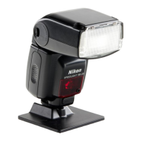
Overview of core technical features and capabilities.

Custom Function Settings

Details on user-configurable flash settings.

Disassembly Guide

Disassembly Procedures Overview

Introduction to the disassembly process.

SB-600 Adjustment Procedures

Required Equipment for Adjustment

List of tools and software needed for calibration.

Inspection and Adjustment Process

Steps for inspecting and adjusting flash functions.

Detailed SB-600 Specifications

Performance Characteristics

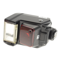
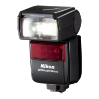
Technical data including guide number, flash distance, and coverage.

Operational Modes and Compatibility

Details on flash modes, creative lighting, and compatible cameras.

SB-600 Features and Operation

Baunce Capability and Power Source

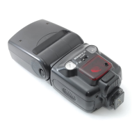
Information on flash head movement and power source.

Operational Indicators and Settings

Details on ready-light, flash duration, and custom settings.

Custom Function Configuration

Custom Setting Descriptions

Explanation of available custom function options.

Setting Custom Functions

Step-by-step guide to changing custom settings.

Disassembly: Exterior Components

Side Rubber and Leg Unit Removal

Steps to detach side rubber and leg unit.

Disassembly: F Case Unit

F Case and Battery Lid Removal

Steps to detach the F case and battery lid.

Disassembly: Head Unit

Head Unit and Fiber Optics Separation

Instructions for disconnecting head unit connectors and fiber optics.

Disassembly: Battery Case and PCBs

Battery Case Unit and PCB Removal

Steps to separate the battery case and remove PCBs.

Disassembly: Internal PCBs and Fuse

Battery-PCB, Thermal Fuse, and R-PCB Removal

Guide to remove battery-PCB, thermal fuse, and R-PCB.

Disassembly: Housing Components

L-Case, Bounce Case F, and Bounce Case R Removal

Steps to remove L-case, bounce case F, and bounce case R.

Disassembly: Bounce Case and Condenser

Bounce Case R and Main Condenser Separation

Steps to separate bounce case R and remove main condenser.

Disassembly: Motor and Lighting Units

Motor Unit, ZOOM-PCB, and Lighting Unit Removal

Guide to remove motor unit, ZOOM-PCB, and lighting unit.

Disassembly: Lighting Unit Components

Lighting Unit Part Removal

Steps for removing springs, shafts, retainers, and PCBs.

Disassembly: Xe Tube and PCBs

Xe Tube and Xe-K PCB Removal

Steps to remove the Xe tube and Xe-K PCB.

Assembly: Lighting Unit

Lighting Unit Component Assembly

Steps for assembling conductive tape, reflector, and Xe-tube.

Assembly: Lighting Unit Components

PCB, Trigger Coil, and Glass Panel Assembly

Guide to assemble PCBs, trigger coil, and glass panel.

Assembly: Motor Unit

Motor Unit and Lighting Unit Integration

Steps for assembling zoom shaft, motor holder, and integrating lighting unit.

Assembly: ZOOM PCB and U Case

ZOOM PCB Wiring and U Case Attachment

Steps for wiring ZOOM PCB and attaching to U case.

Assembly: Main Condenser

Main Condenser Wiring and Mounting

Steps for wiring and mounting the main condenser.

Assembly: Bounce Case R

Bounce Case R Component and U Case Assembly

Steps for assembling bounce case R parts and integrating with U case.

Assembly: Main Condenser and Bounce Case

Main Condenser Integration with Bounce Case

Specific steps for assembling the main condenser with bounce case.

Assembly: Bounce Case F and L Case

Bounce Case F and L Case Assembly

Steps for assembling bounce case F, ring, and L case.

Assembly: R Case Unit

R Case Unit Component Assembly

Instructions for assembling various parts into the R case unit.

Assembly: R-PCB and Battery Case

R-PCB and Battery Case Assembly

Steps for attaching R-PCB and assembling the battery case unit.

Assembly: Thermal Fuse and Battery PCB

Thermal Fuse and Battery PCB Attachment

Steps for attaching the battery PCB and thermal fuse.

Assembly: F-PCB and L-PCB

F-PCB and L-PCB Wiring and Case Attachment

Steps for wiring and attaching PCBs to the case.

Assembly: Battery Case to R Case Unit

Connecting and Mounting Battery Case Unit

Steps to connect and assemble the battery case unit.

Assembly: Head Unit Connection

Connecting Head Unit and F Case to R Case

Steps to connect head unit and F case to R case.

Assembly: Final Housing Integration

Combining Housing Components and Wire Routing

Steps to combine main components and arrange wires.

Assembly: Leg Unit

Leg Unit Attachment and Connections

Steps for attaching the leg unit and making connections.

Assembly: Side Rubber Attachment

Attaching Side Rubbers

Steps to attach the right and left side rubbers.

Adjustment Procedures Overview

Required Equipment and Software

List of necessary tools and software for calibration.

Inspection and Adjustment Process

Overview of inspection and adjustment steps.

Flash Adjustment Precautions

Environment and Reflector Guidelines

Important environmental and equipment setup for accurate adjustment.

PC and SB Connection for Adjustment

Serial Communication Setup

Steps to connect PC to SB via serial port.

PC and SB Connection via USB

USB Communication Setup

Steps to connect PC to SB via USB.

USB Driver Installation

Driver Download and Installation

Guide to download and install the necessary USB driver.

Adjustment Software Operations

Software Installation and Usage

Procedure for installing and operating the adjustment software.

Focusing Light Adjustment

Focusing Light Test Setup and Procedure

Preparations and steps for adjusting the AF assist illuminator.

Focusing Light Inspection Chart

SB-600 Circuitry Overview

Core Circuit Components

Overview of main circuits like battery, pressurization, and safety.

Control and Interface Circuits

Details on flash control, custom IC, and data communication.

Detailed Circuitry Functions

Custom IC Sub-circuits

Explanation of sub-circuits within the Custom IC.

Metering and Communication Circuits

Details on metering, TG, STP, AF assist, and data communication.

Circuitry: Control and Peripherals

CPU, LCD, LED, and Motor Drive Functions

Functions of the CPU, LCD, LED, and motor drive.

Input/Output and External Interfaces

Details on switch input, leg contacts, AF LED, buzzer, and SC-29.

SB-600 System Block Diagram

EEPROM Data Map

R-PCB Component Layouts

F-PCB and L-PCB Component Layouts

Other PCB Layouts

C, ZOOM, FOOT PCB Layouts

Component layout for C, ZOOM, and FOOT PCBs.

BOUNCE, XE-A, XE-K PCB Layouts

Component layout for BOUNCE, XE-A, and XE-K PCBs.

SB-600 Circuit Diagram

SB-600 Wiring Diagram

Required Tools and Equipment

Communication and Software Tools

List of communication tools and software.

Measurement and Computer Equipment

List of measurement devices and computers.

Consumables and Adhesives

Grease, Tape, and Sealants

Details on lubricants, tapes, and adhesives.

SB-600 Parts List Introduction

Exploded View: Main Body Assembly (Fig. 1)

Exploded View: Flash Head Assembly (Fig. 2)

Exploded View: Internal Components (Fig. 3)

Exploded View: Base and Housing (Fig. 4)

Exploded View: Sub-assemblies (Fig. 5)

SB-600 Parts List - Section 1

SB-600 Parts List - Section 2

SB-600 Parts List - Section 3

SB-600 Parts List - Section 4

SB-600 Parts List - Section 5

SB-600 Parts List - Section 6

SB-600 Parts List - Section 7

SB-600 Parts List - Section 8

Related product manuals