Do you have a question about the Nilfisk-Advance Core 125 and is the answer not in the manual?
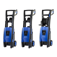
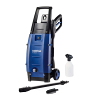
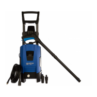
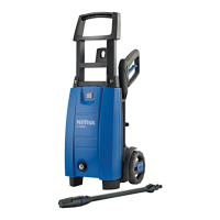
Details the assembly of external cabinet components for Core models.
Details the assembly of internal pump unit components for Core models.
Step-by-step guide for removing the rear cabinet part of Core 125/130.
Instructions for disassembling and reassembling the switch box on Core 125.
Instructions for disassembling and reassembling the switch box on Core 130/140.
Guide for removing and installing the start/stop valve on Core 125/130.
Procedure for changing seals and valves within the pump assembly.
Critical guidance on correct positioning of valve bodies during assembly.
Specific safety checks for switch box assembly on the Core 125 model.
General safety checks for switch box assembly on the main cabinet.
Specific safety checks for switch box assembly on Core 130/140 models.
General safety checks for switch box assembly on the main cabinet.
Step-by-step guide for reassembling the rear cabinet part of Core 125/130.
Instructions for pairing wireless handles with the machine.
Procedure for replacing the battery in the wireless handle.
Specifies torque values for pump assembly components on Core 125/130.
Specifies torque values for cabinet assembly screws on Core 125/130.
Lists recommended and alternative oil types for the pump.
Lists approved alternative oil brands and types for the pump.
Specifies recommended lubricants for O-rings and seals.
Lists specific tools recommended for valve seat maintenance.
Overview of the start/stop system logic for Core models.
Describes the system state when no pressure is present and the machine is off.
Illustrates the pressure build-up process when the machine starts.
Describes pressure build-up when the gun is closed and the micro switch activates.
Explains the system state and pressure when the motor stops.
Describes the system state when the gun is open and the motor starts on Core 125.
Details the system state during normal operation of Core 125.
Describes the system state when the gun is open and the motor starts on Core 130.
Details the system state during normal operation of Core 130.
Electrical schematic for the Core 125 model, showing components and connections.
Electrical schematic for Core 130/140 models, including PCB and speed control.
| Pump Pressure | 125 bar |
|---|---|
| Voltage | 220-240 V |
| Frequency | 50-60 Hz |
| Water Flow Qmax | 460 L/h |
| Hose Length | 5 m |
| Max. Inlet Temperature | 40 °C |
| Weight | 6.6 kg |
| Cable Length | 5 m |
| Motor Power | 1500 W |
| Rated Power | 1.5 kW |