7
41840-A McAlby Court, Murrieta, CA 92562
(800) 451-9343, www.nimbuswater.com
CS-2 Feed and Drain Connec ons
Fig. 3
Fig. 4
Fig. 2
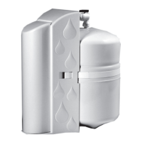
Feed Connec on
1. Locate and turn off the angle stop valve on the cold water line feeding the sink where
the system is to be installed. This valve will usually be located under the sink on the
pipe coming out of the wall.
2. When the angle stop valve is closed, relieve pressure in the line by opening the cold
water tap on the sink.
3. To install the feed adapter at the faucet connector, disconnect the cold water feed line
where it connects to the faucet inlet connector. This will usually require an open end
wrench, pliers, or long reach faucet wrench.
4. Take the 1/4" feed connector from the parts kit and install it into the brass feed con-
nector adapter. Use a crescent wrench or open-end wrench to ghten the connector
into the adapter. See Fig. 2.
5. Using the fl at and cone washers as neces sary, install the feed adapter into the faucet
inlet connector. Then reconnect the cold water feed line to the open end of the feed
adapter. Tighten all connec ons securely.
6. Using the 1/4" tubing, install the compression nut, plas c ferrule, and plas c tube
insert. Secure the tubing into the feed connector. Tighten the tubing retain ing nut
securely.
7. Obtain the small feed valve warning tag from the parts bag and a ach it by its wire
es to the feed valve.
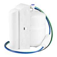
Drain Connec on
Note: The drain saddle assembly must be installed before the 'P' trap. Do not install the
drain saddle assembly between the 'P' trap and the wall.
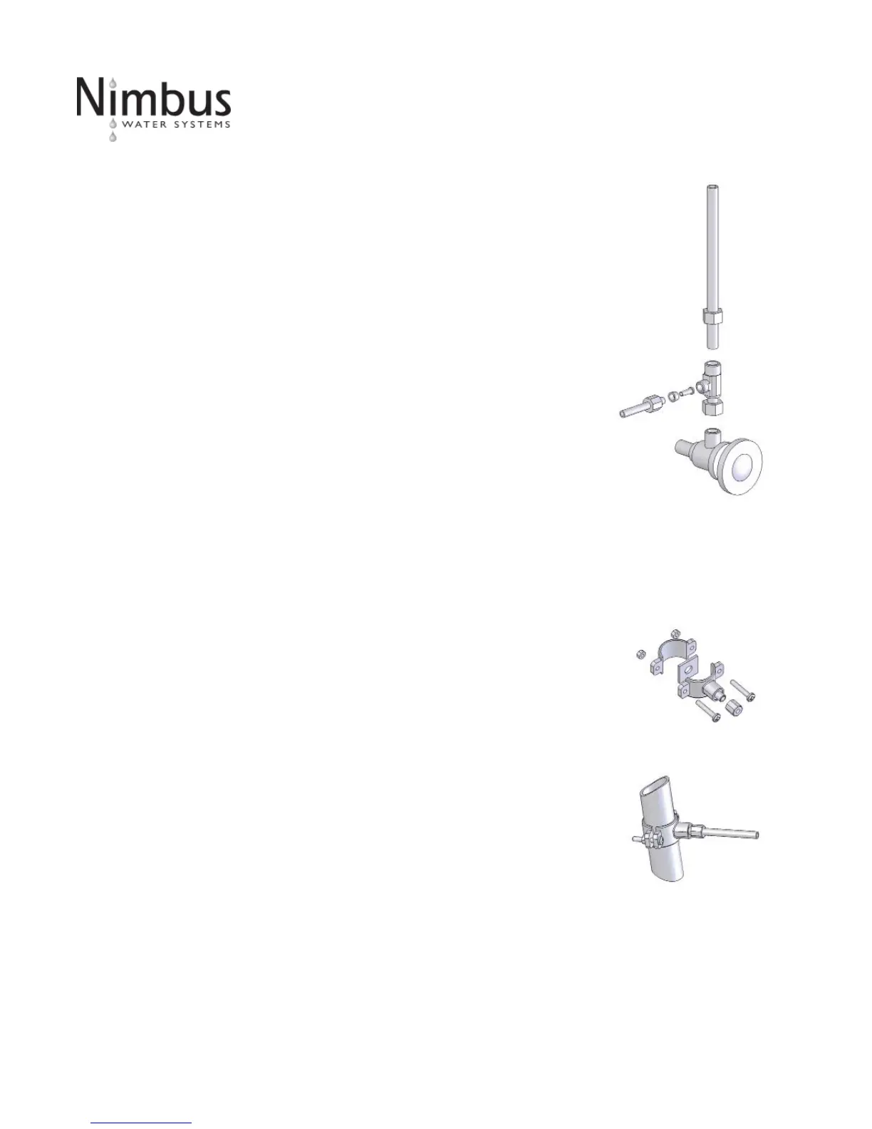
1. Posi on drain saddle assembly (Fig. 3) on drain pipe under sink between the P trap
and the sink connec on.
2. Orient the drain saddle so that the connec tor opening points in the general direc on
of the planned loca on for the R.O. dispensing faucet.
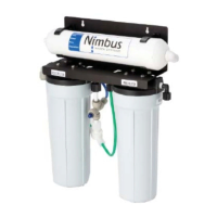
3. Screw the connector nut onto the drain saddle threaded connector loosely (Fig. 4).
Using the connector opening in the side of the drain saddle as a guide, drill a 3/8" hole
through the wall of the drain pipe.
4. Remove drain saddle assembly. Place the adhesive foam pad over the 3/8" hole in
the drain pipe. Replace the assembly onto the drain pipe, aligning the hole in the drain
with the hole in the drain assembly.
5. Tighten the saddle bolts evenly on both sides un l the saddle grips the pipe snugly -
do not over ghten. (Fig.4)
 Loading...