ENGINE UNIT
EM-103
< UNIT DISASSEMBLY AND ASSEMBLY >
[VQ40DE]
C
D
E
F
G
H
I
J
K
L
M
A
EM
N
P
O
Disassembly and Assembly INFOID:0000000008799004
DISASSEMBLY
NOTE:
The following procedures explain how to disassemble the engine with the engine stand fastened to the bell
housing. Some steps may be different if using a different type of engine stand.
1. Remove engine assembly from vehicle. Refer to EM-99, "Removal and Installation"
.
2. Remove both exhaust manifolds. Refer to EM-31, "Removal and Installation (Exhaust Manifold)"
.
3. Remove the generator. Refer to CHG-27, "Removal and Installation"
.
4. Remove the parts that may restrict installation of engine to engine stand.
a. Remove clutch cover and clutch disc (M/T models). Refer to CL-15, "Removal and Installation"
.
b. Remove flywheel (M/T models) or drive plate (A/T models).
• Holding crankshaft pulley bolts, lock crankshaft to remove fly-
wheel or drive plate bolts.
• Loosen bolts diagonally.
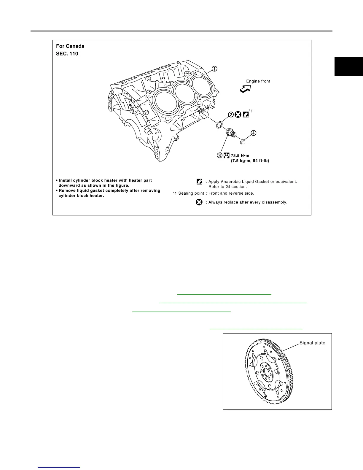
CAUTION:
• Be careful not to damage or scratch drive plate (A/T mod-
els) and contact surface for clutch disc of flywheel (M/T
models). Especially avoid deforming and damaging of sig-
nal plate teeth (circumference position).
• Do not disassemble drive plate.
• Place the drive plate with signal plate surface facing other
than downward.
• Keep magnetic materials away from signal plate.
1. Cylinder block 2. Gasket 3. Cylinder block heater
4. Connector protector cap
PBIC2936E
KBIA2491E
Revision: January 2013 2013 Xterra