ENGINE UNIT
EM-105
< UNIT DISASSEMBLY AND ASSEMBLY >
[VQ40DE]
C
D
E
F
G
H
I
J
K
L
M
A
EM
N
P
O
8. Remove cylinder heads. Refer to EM-88, "Removal and Installation".
9. Remove sub harness, and remove knock sensors.
CAUTION:
Handle sensor carefully; do not shock or drop.
10. Remove piston and connecting rod assembly as follows:
• Before removing piston and connecting rod assembly, check the connecting rod side clearance. Refer to
EM-112, "Inspection After Disassembly"
.
CAUTION:
Be careful not to drop connecting rod bearing or to scratch the bearing surface.
11. Position crankshaft pin corresponding to connecting rod to be removed onto the bottom dead center.
12. Remove connecting rod bearing cap.
13. Push piston and connecting rod assembly out of the cylinder
head side using suitable tool.
CAUTION:
Be careful not to damage the cylinder wall or crankshaft pin
resulting from an interference of the connecting rod big
end.
14. Remove connecting rod bearings from connecting rod and connecting rod bearing cap.
CAUTION:
Identify installation position, and store them without mixing them up.
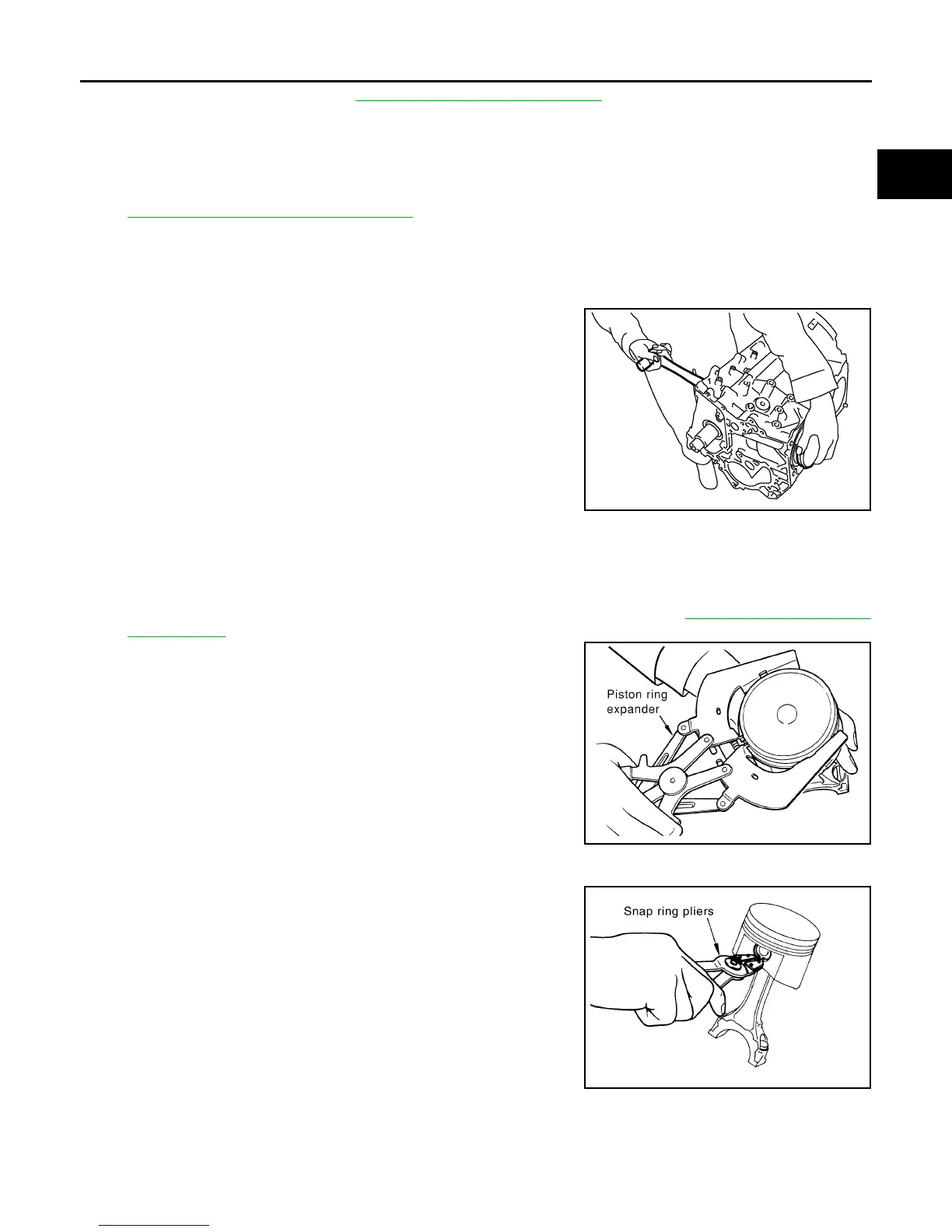
15. Remove piston rings from piston.
• Before removing piston rings, check the piston ring side clearance. Refer to EM-112, "Inspection After
Disassembly".
• Remove piston rings using piston ring expander or suitable
tool.
CAUTION:
• When removing piston rings, be careful not to damage
piston.
• Be careful not to damage piston rings by expanding them
excessively.
16. Remove piston from connecting rod as follows:
a. Remove snap ring using snap ring pliers.
PBIC2940E
PBIC0087E
PBIC1638E
Revision: January 2013 2013 Xterra