EM-58
< REMOVAL AND INSTALLATION >
[VQ40DE]
FRONT TIMING CHAIN CASE
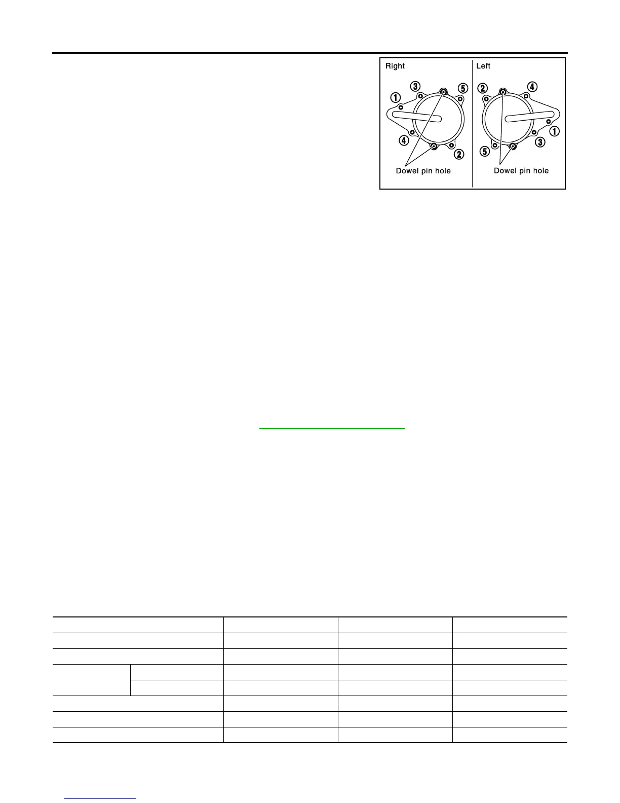
e. Tighten bolts in numerical order as shown.
8. Install crankshaft pulley as follows:
a. Install crankshaft pulley, taking care not to damage front oil seal.
• When press-fitting crankshaft pulley with plastic hammer, tap on its center portion (not circumference).
b. Tighten crankshaft pulley bolt in two steps.
c. Remove Ring Gear Stopper Tool.
9. Rotate crankshaft pulley in normal direction (clockwise when viewed from front) to confirm it turns
smoothly.
10. Installation of the remaining components is in the reverse order of removal.
INSPECTION AFTER INSTALLATION
• Before starting engine, check oil/fluid levels including engine coolant and engine oil. If less than required
quantity, fill to the specified level. Refer to MA-13, "Fluids and Lubricants"
.
• Use procedure below to check for fuel leakage.
• Turn ignition switch ON (with engine stopped). With fuel pressure applied to fuel piping, check for fuel leak-
age at connection points.
• Start engine. With engine speed increased, check again for fuel leakage at connection points.
• Run engine to check for unusual noise and vibration.
NOTE:
If hydraulic pressure inside timing chain tensioner drops after removal and installation, slack in the guide
may generate a pounding noise during and just after engine start. However, this is normal. Noise will stop
after hydraulic pressure rises.
• Warm up engine thoroughly to make sure there is no leakage of fuel, exhaust gas, or any oils/fluids including
engine oil and engine coolant.
• Bleed air from passages in lines and hoses, such as in cooling system.
• After cooling down engine, again check oil/fluid levels including engine oil and engine coolant. Refill to spec-
ified level, if necessary.
• Summary of the inspection items:
*Power steering fluid, brake fluid, etc.
PBIC0918E
Step 1 : 44.1 N·m (4.5 kg-m, 33 ft-lb)
Step 2 : 84° - 90° degrees clockwise
Tool number : KV11105210 (J-44716)
Item Before starting engine Engine running After engine stopped
Engine coolant Level Leakage Level
Engine oil Level Leakage Level
Transmission/
transaxle fluid
A/T and CVT Models Leakage Level/Leakage Leakage
M/T Models Level/Leakage Leakage Level/Leakage
Other oils and fluids* Level Leakage Level
Fuel Leakage Leakage Leakage
Exhaust gas — Leakage —
Revision: January 2013 2013 Xterra