CAMSHAFT
EM-83
< REMOVAL AND INSTALLATION >
[VQ40DE]
C
D
E
F
G
H
I
J
K
L
M
A
EM
N
P
O
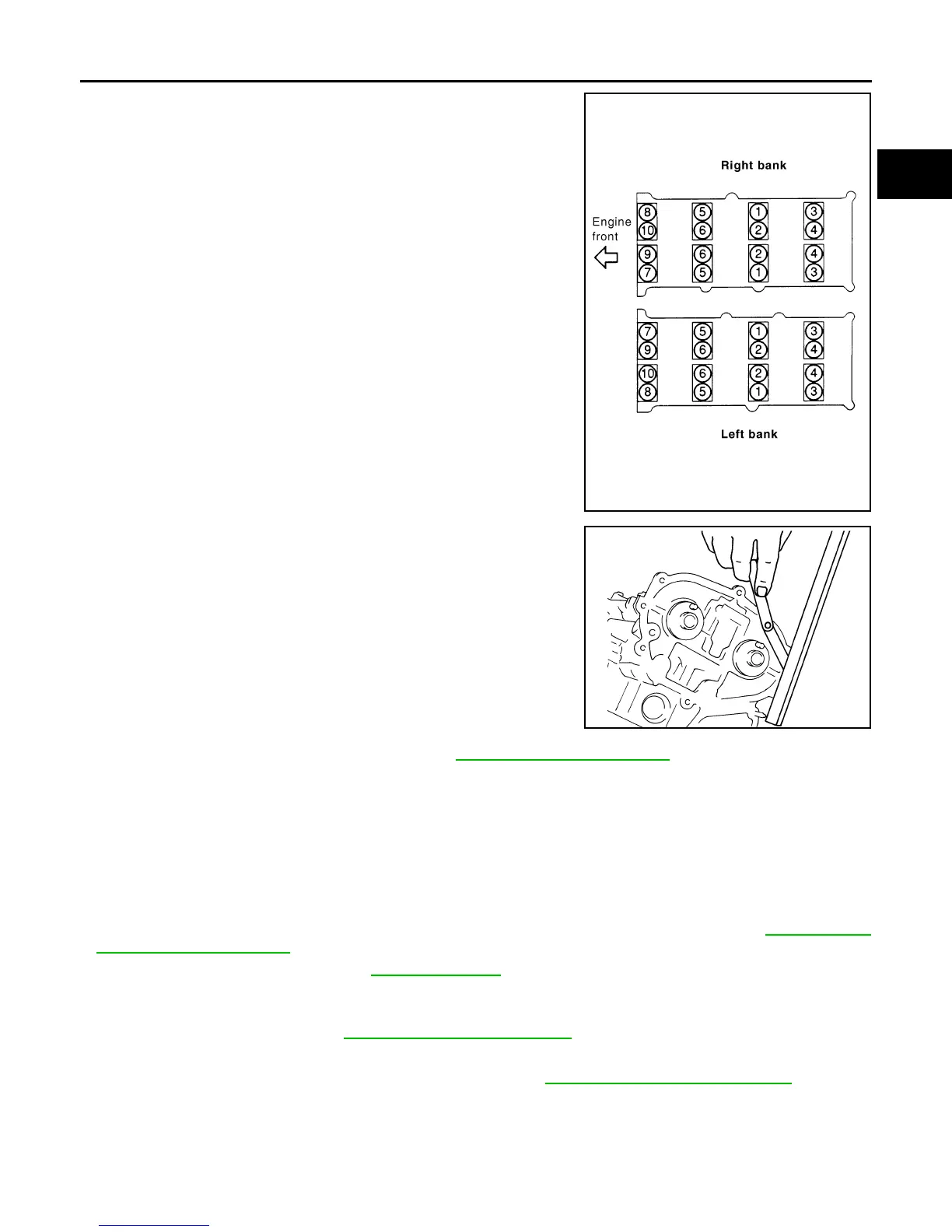
5. Tighten camshaft bracket bolts in the following steps, in numeri-
cal order as shown.
6. Measure the difference in levels between front end faces of
camshaft bracket (No. 1) and cylinder head.
• Measure two positions (both intake and exhaust side) for a
single bank.
• If the measured value is out of the standard, re-install cam-
shaft bracket (No. 1).
7. Check and adjust the valve clearance. Refer to EM-129, "Standard and Limit"
.
8. Installation of the remaining components is in the reverse order of removal.
INSPECTION AFTER INSTALLATION
Inspection of Camshaft Sprocket (INT) Oil Groove
WARNING:
• Check when engine is cold so as to prevent burns from any splashing engine oil.
CAUTION:
• Perform this inspection only when DTC P0011 or P0021 are detected in self-diagnostic results of
CONSULT and it is directed according to inspection procedure of EC section. Refer to EC-174, "DTC
Confirmation Procedure".
1. Check the engine oil level. Refer to LU-7, "Inspection"
.
2. Perform the following procedure so as to prevent the engine from being unintentionally started while
checking.
a. Release fuel pressure. Refer to EC-491, "Fuel Pressure Check"
.
b. Disconnect the harness connectors from ignition coil and injector.
3. Remove intake valve timing control solenoid valve. Refer to EM-51, "Removal and Installation"
.
Camshaft bracket bolts
Step 1 (bolts 7 - 10) : 1.96 N·m (0.2 kg-m, 17 in-lb)
Step 2 (bolts 1 - 6) : 1.96 N·m (0.2 kg-m, 17 in-lb)
Step 3 (bolts 1 - 10) : 5.88 N·m (0.6 kg-m, 52 in-lb)
Step 4 (bolts 1 - 10) : 10.4 N·m (1.1 kg-m, 92 in-lb)
PBIC2050E
Standard : –0.14 to 0.14 mm (–0.0055 to 0.0055 in)
EMQ0044D
Revision: January 2013 2013 Xterra