Installation & Setup
Equipment Requirements & Mounting: The process for employing the ER8500C is rather quick
and simple. A common topology involves up to eight (8) existing coax cables (up to but not
exceeding 1,640ft/500m), up to eight (8) ET1500C transmitters, up to eight (8) IP cameras or other
peripheral network devices (both universally referred to as the Power Device(s)or PDs), the rack
mounted ER8500C (which can be referred to as the NITEK Power Sourcing Equipment/PSE). The
ER8500C NITEK PSE is both 802.3af and 802.3at compliant. That is it produces 15.4 W 48VDC @
350mA of 802.3af as well as 25.5W 60VDC @ 600mA of 802.3at PoE+ power for proper attached
device operation. Additionally, all RJ45 terminations are in accordance with 568B pinout standards.
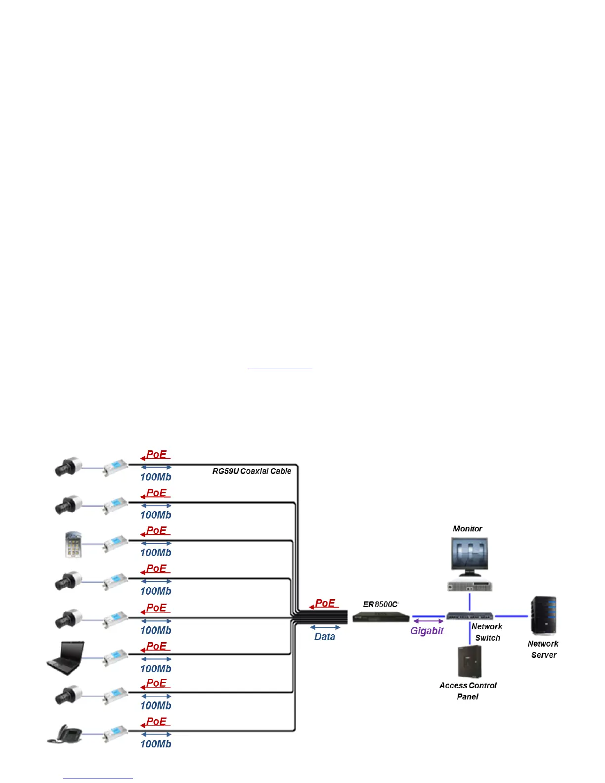
The method for facilitating Ethernet communication and PoE flow over RG59U cable starts with
connecting the ER8500C NITEK PSE to a series of up to eight (8) coax cables via the coax BNC
connectors. The coax cables interface with the PDs via the ET1500C (up to 8) transmitters. The IP
camera (s)/ PDs establish connectivity to ET1500Cs via RJ5 jacks and a CAT5e/CAT6 patch cords.
The ER8500C powers itself and all attached devices within in this network/system. The IP data from
the PDs is transmitted over each individual coax cable(s) through the ET1500C(s) to the rack
mounted ER8500C in either the IDF or MDF. The aggregate PD data is transmitted to the greater
LAN or WAN via the 1 gigabit LAN port located at the rear of the NITEK PSE. An illustration of this is
represented below in the “Installment Topology” diagram.
Upon final termination the devices will undergo initialization and auto-configuration processes (see
LED Indicator chart on pg.#7) which may take a number of seconds (time variations are
device/installation/topology parameter dependent) to complete before PoE and Ethernet
communication commences. For optimal performance referring to the PoE/distance chart (see
pg.#6) and adhering to the IP camera/PD operational specifications is recommended. If issues arise
during the installation process please see the “Trouble Shooting Tips” section (pg # 7). You may also
contact our web based live tech support at: www.nitek.net
or call 1-(800)528-4343 in order to speak
with one of our engineers directly.
Installment Topology
 Loading...