Indicate current address
1. Turn the power switch ON.
a) For one second, all LED’s are lit and the buzzer
sounds.
2. Press the [Search] Key
a) Buzzer sounds, then the EVA-AD2 starts
transmitting to the device.
b) Do not remove the device when transmitting, or
damage could result.
3. The 7 segment LED reads [Customer code], [Type of
device], [Address] in turn.
a) The buzzer sounds, ERROR LED lights and the 7
segment LED display’s an ERROR CODE when an
unsupported or defective device is connected.
0.1 0 → 1 2.3 → 0 0 3.
↑ ↑ ↑
Customer code Type of device Address
【Note - Dot position】
The 7 segment LED is distinguishes the Customer Code,
Type and Address by the dot position in the LED.
The information displayed by the 7 segment LED cycles
every second and stops whilst displaying the [address] at the
end of the second cycle.
Type of device is assigned to the detectors, the modules and
the base as below.
EVA-MiniIP: 54 EVA-PYH: 153
EVA-DIP: 85 EVA-PY: 152
EVA-DOP: 86 EVA-H2-H: 134
EVA-DOP-240V: 87 EVA-H2: 133
EVA-SCM: 66 EVA-DPH: 154
EVA-ZMU: 18 EVA-S6 Base: 120
Pressing any key at any time during the information
collection cycle, forces the EVA-AD2 to display the address,
and await new address selection.
Set new address
1. +100, +10, +1 keys are used to select the new address.
2. Press the [Set] key
a) The buzzer sounds, and all LED’s are turned off.
The EVA-AD2 then starts transmitting to the
detector.
b) Do not remove the detector.
3. The 7 segment LED shows the new address and “complete”
LED lights.
If an unsupported or defective device is connected the
buzzer sounds , ERROR LED is lit and the 7 segment LED
reads ERROR CODE.
4. To continue changing the address for another detector,
change the detector and then repeat from paragraph 3.
To finish changing addresses, turn the POWER SW off.
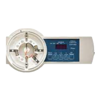
6. Connection Method
For detector
Figure 1: Mounting a detector on EVA-AD2
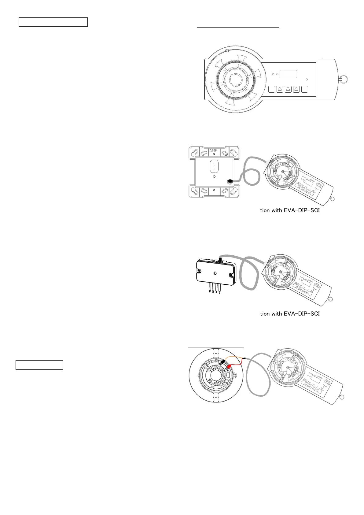
For module (Type:EVA-DIP-SCI)
Figure 2: Connection with EVA-DIP-SCI
For module (Type:EVA-MiniIP)
Figure 3: Connection with EVA-DIP-SCI
For EVA-S6 Base
Connect the red alligator clip to the terminal 1 of EVA-S6
Base and the black alligator clip to the terminal 6.
Figure 4: Connection with EVA-AD2 and EVA-S6 Base
110100
ADDRESS
ERROK
Set
Address
+1+10+100
Power
Search
Address
Address
Programmer
EVA-AD2
 Loading...