8
nixiediy@gmail.com
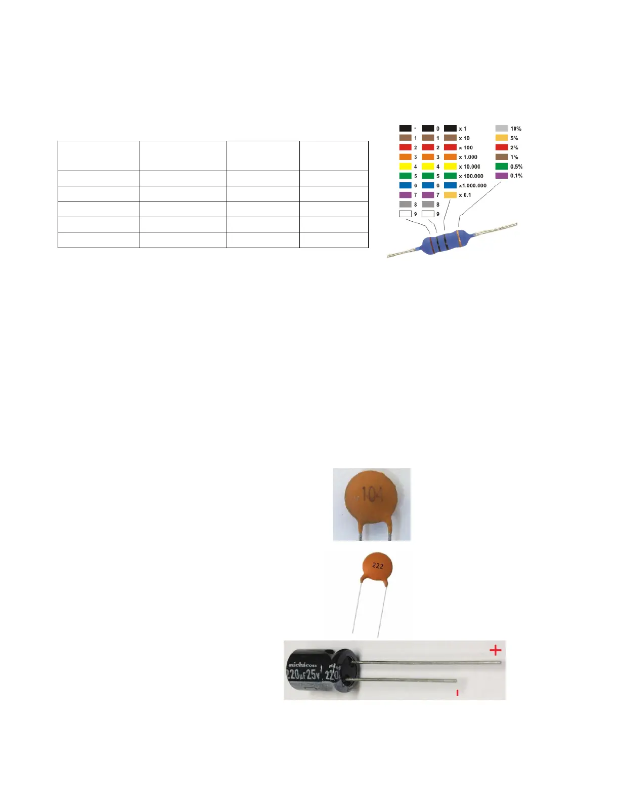
The resistors used in the kit are marked with four coloured bands to identify the value. Bands 1 and 2
identify the first two digits, band 3 is the Multiplier and band 4 is the tolerance.
The first, second and third coloured bands on the resistors indicate the resistance using a colour code.
This table indicates how to convert each colour to its numerical equivalent. Gold band means 5%
tolerance.
To read a resistor code, first locate the gold band and read the colours in order from the other end.
(All resistors in this kit have a gold band indicating 5% tolerance.) The first two bands indicate digits in
the resistance; the third band (called the multiplier) indicates the number of zeroes to be added to
the digits to obtain the resistance. However, it is sometimes unclear in which direction the bands
should be read. Therefore, we recommend that the resistors will be identified with a multimeter.
Use the resistor code to identify and sort all of the resistors. One good way to keep them sorted is to
tape one end to a piece of paper and write the resistance and component number (R1, R2, etc.). Once
you have identified and sorted all of the resistors, you are ready to solder them to the PCB. To
prepare a resistor for insertion into the board, bend the two leads so that they form a right angle to
the resistor body.
Capacitors
0.1uF (Code 104), (C2, C4, C6, C7)
2.2nF (Code 222), (C3)
220uF 25V, (C1)
 Loading...