Do you have a question about the Noblelift CG1646 and is the answer not in the manual?
General safety precautions for maintenance operations.
Tables for converting various measurement units.
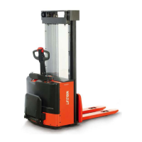
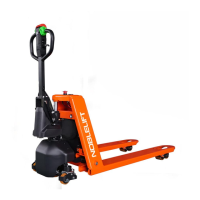
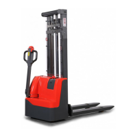
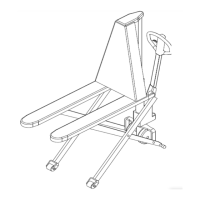
Identifies various parts of the stacker with numbers and names.
Contains technical features and residual capacity data.
Details on hydraulic oil, lubrication chart, and grease specifications.
Wiring diagrams, connection diagrams, and component lists for the electric system.
Details on cable systems, parts lists, and components.
Specifications for drive wheel, pump station, and battery.
Initial, balanced, and common charging procedures, including sulfuric acid specs.
Charger wiring, electrical characteristics, and operating procedures.
Controller connections, parameters, and troubleshooting.
Battery indicator, hour meter logic, discharge adjustments, and troubleshooting.
Steps for replacing various electric components like battery, controller, and fuses.
Figures and applications of tools for electric plug repair.
Diagram illustrating hydraulic flow and guidelines for inspecting hydraulic oil.
Procedures for operating, replacing, cleaning, and troubleshooting the pump station.
Steps for removing and replacing the hydraulic cylinder.
Exploded view and parts list for the drive wheel assembly.
Steps for dismantling and replacing the drive wheel.
Steps for dismantling the motor and replacing carbon brushes.
Steps for replacing the brake and adjusting its clearance.
List of parts for the control handle assembly.
Steps for accessing electric parts within the handle and operating related components.
Steps for replacing accelerator, air spring, and micro switch.
Steps for dismantling the internal mast, including hydraulic pipe and micro switch.
Schedule of maintenance tasks and their intervals.
Troubleshooting flowchart for various operational issues.
| Brand | Noblelift |
|---|---|
| Model | CG1646 |
| Category | Lifting Systems |
| Language | English |