After Sales
Technical Documentation
Desktop Charger CHH–2
Page – 6
Original 50/96
Circuit Description
The DC2 desktop charger module consists of microcomputer based con-
trol logic for spare battery charging and discharging. It also has power
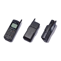
outlet for transportable phone.
Control Logic
Charging is controlled by processor D150. It is a single–chip type control-
ler incorporating RAM, ROM, A/D converter, and a multifunction timer/
counter.
Prosessor Input/Output Signals
Name: Function:
PA0 Phone LED control, green: ”1”
PA1 Phone LED control, red: ”1”
PA2 Spare battery LED control, green: ”1”
PA3 Spare battery LED control, red: ”1”
PA4/DBIN Discharge button input, ”0”: start discharge
PA5/DISW Discharge control output, ”1”: discharge enabled
PA6/BSW Spare battery charge control, ”0”: charge disabled,
”1”: rapid charge, PWM: pulsed mode
PC7 Watchdog reset output
Processor A/D Inputs
Name: Function:
AN0/VBATL Battery voltage
• range: 0...11 V
• resolution: 43 mV/bit
AN1/VBATH High resolution battery voltage
• range 7...11 V
• resolution: 16 mV/bit
AN2/PDET Phone current detect
• PDET = ”1” for A/D value higher than 5
• PDET = ”0” for A/D value 5 of or less
AN3/BTEMP Battery temperature, 27 kΩ pull–up resistor to
+5 V reference voltage
AN4/BSI Battery size, 100 kΩ pull–up resistor to +5 V
reference voltage