nokia
CONNECTING PEOPLE
PAGE 15 (23) Approved 1.0
CMO Operations & Logistics
DJk
WW Service Solutions & Development
Bochum / Germany CONFIDENTIAL 16.02.2005
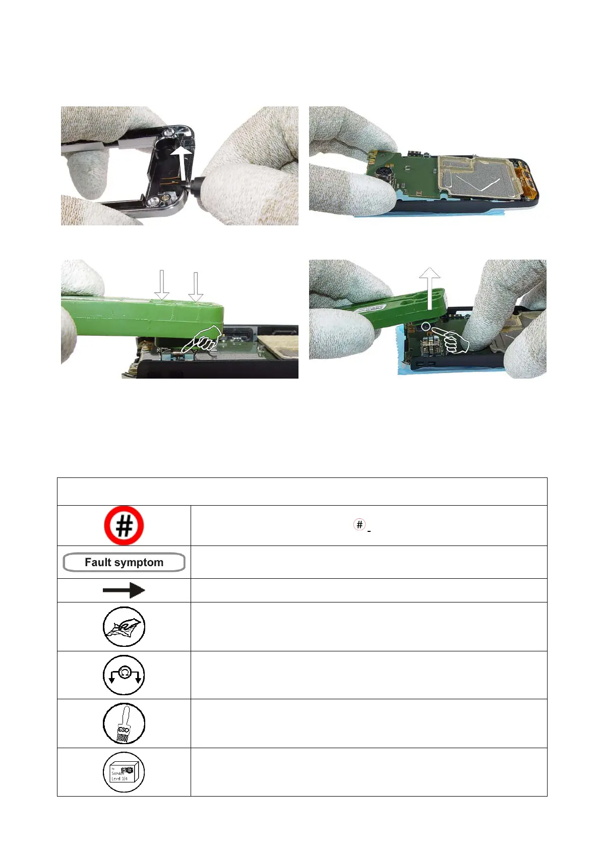
25) Now remove the DC-Jack by using the DC-plug.
26) Use the A-Cover and the C-Cover as a support for
the UI-Board when removing the Camera.
27) Release the clips of the camera holder by using the
camera removal tool SS-15.
28) Remove the Camera and note the guide pin when
re-assembling the device.
10. LEGEND FOR QUICK TROUBLE SHOOTER
This legend is valid for all parts of the Quick Trouble Shooter
Follow the steps until the problem is solved. If this doesn’t help, you are not authorized to go forward.
Only marked components ( e.g. I002
) can be changed.
The start point of repair activities regarding the appeared fault symptoms.
Follow the arrows step by step
Pads or contacts: Check optical and mechanical condition particularly regarding
to corrosion. Clean if necessary.
Measure component for electrical functionality and change, if needed.
(Level 2 only)
Pads or contacts: Check optical and mechanical condition particularly regarding
to corrosion. Clean with ESD brush only, if necessary.
No more actions possible send product to the appropriate service supplier with
higher service level.
Service Manual 3230 Level 1&2 Copyright © 2005 Nokia Corporation. All rights reserved.
 Loading...