PAMS
Technical Documentation
NSE–3
Disassembly & Troubleshooting Instructions
Page 17
Original, 11/97
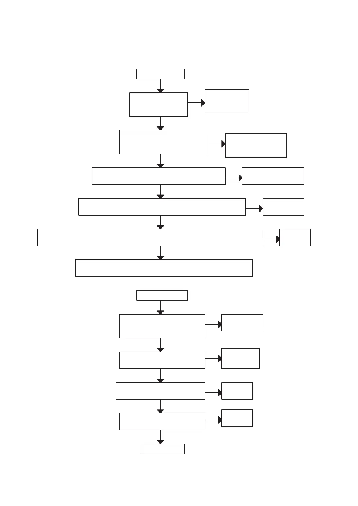
SIM Card failure
Insert SIM card fault
Voltage level < 1.5 V
at pin 95 of D200 when
YES
NO
Check
R120, R122, X101
C120, C160
YES
BSI resistor is connected
VSIM, DATA, RESET and CLOCK lines
rises up to 5 V after power on at pins
of SIM card
NO
YES
Check
SIM card and SIM reader
connectors
VSIM(36), DATAO(43),SIMRSTO(42) and SIMCLKO(38) lines
rises up to 5 V after power on at pins of N100 (CCONT)
NO
YES
Check
X302, R124, R125, R128
SIMPWR(30), DATAA(44), SIMRSTA(40), SIMCLK(41) and SIMIOC(39) lines
rises up to 2.8 V after power on at pins of N100 (CCONT)
YES
faulty circuit
N100 (CCONT)
NO
SIMCardPwr(129), SIMCardData(120), SIMCardRstX(127), SIMCardClk(126) and SIMCardIOC(128) lines
rises up to 2.8 V after power on at pins of D200 (MAD2)
NO
YES
faulty PCB
Check again that voltage level at pin 95 (SIMCardDetX) of D200 is lower than 1.5V
If it is, change D200
Card Rejected fault
YES
VSIM is according the specification
VSIM = 2.8 V min (with 3 V SIM card)
VSIM = 4.5 V min (with 5 V SIM card)
NO
faulty circuit
N100 (CCONT)
YES
The ATR data can be seen at pin 43
(CCONT, N100)
NO
Check
X302, R124
YES
The ATR data can be seen at pin 120
(MAD2, D200)
NO
Check
N100
YES
SIMIOControl line (N100 pin 36) is ”1”
during the ATR message
NO
Check
D200
YES
Check D200
 Loading...