Nokia Asha 201 (RM-799/RM-
Co nf id e nt ial | Co pyrig ht © 2011 Nokia | A ll rights reserved
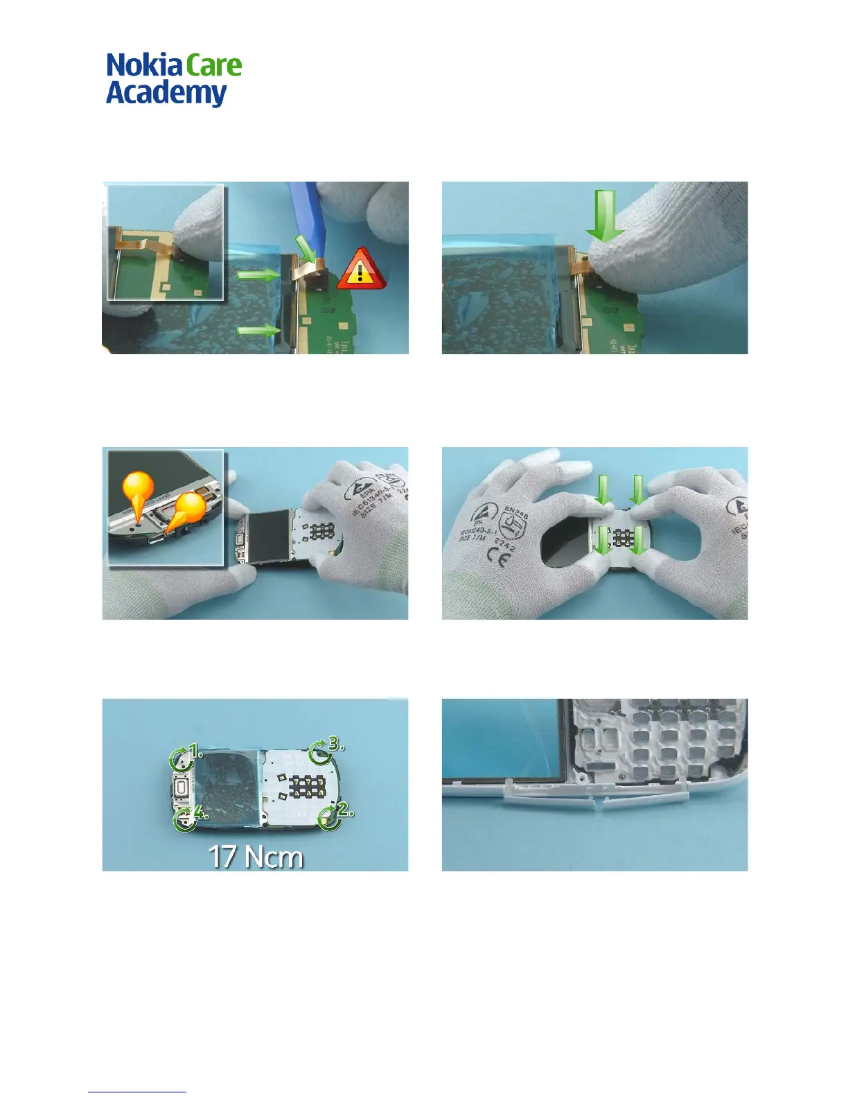
1) Connect the DI SPLAY connector to the ENGI NE
BOARD. Use the sharp end of the SS-93 to bend the
DI SPLAY flex while carefully pushing the DISPLAY to
the direction shown
. Be careful not to bend too close
2) Carefully push down the DISPLAY flex.
3) Star t to assemble the ENGINE BOARD including the
DI SPLAY and the UI FRAME to the B-COVER top side
first. Use the USB connector and the shown pin to get
the right alignment.
4) Push down to attach the ENGINE BOARD including
the DISPLAY and the UI FRAME to the B-COVER.
5) Tighten the four Torx+ size 6 screws to the torque
6) Before assembling the B-COVER to the A-COVER,
open the SD DOOR and the SIM2 DOOR.
 Loading...