N85, RM-333, RM-334, RM-335
Service Manual Level 1&2
ISSUE 1
Confidential
19
11. ASSEMBLY HINTS
• When setting the Back Cover Assy on the Engine Frame Assy, check that the camera lid is in the
closed position. If the camera lid is not closed, the camera switch on the 2
nd
PWB assy will break.
• When setting the Engine PWB on the Engine Frame, make sure that the key lock switch in the Engine
Frame is pushed towards the top half of the phone. If the key lock switch is not in the correct
position, the switch on the PWB will break.
• When assembling the UI (that is, Slide Assy, UI-FPC and the Display), you must use the SS-157
Assembly Jig. Without the SS-157 tool, placing the UI-FPC is difficult.
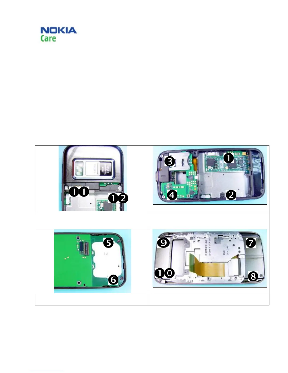
11.1 Screw order and torque
1) Tighten the screws to the torque of 18 Ncm in the
order shown.
2) Tighten screws 1 and 2 to the torque of 6 Ncm and
screws 3 and 4 to the torque of 18 Ncm in the order
shown.
3) Tighten the screws to the torque of 18 Ncm in the
order shown.
4) Tighten the screws to the torque of 6 Ncm in the
order shown.
Copyright @ 2008 NOKIA. All rights reserved

 Loading...