CONFIDENTIAL 14 (25)
NPE-4 6310/NPL-1 6310i Repairhints
Customer Care Europe & Africa Version 1.0 Approved
SCCE Training Group Date 15.08.2002
© NMP 2002
Checked by:
SCCE Training Group
Approved by:
SCCE
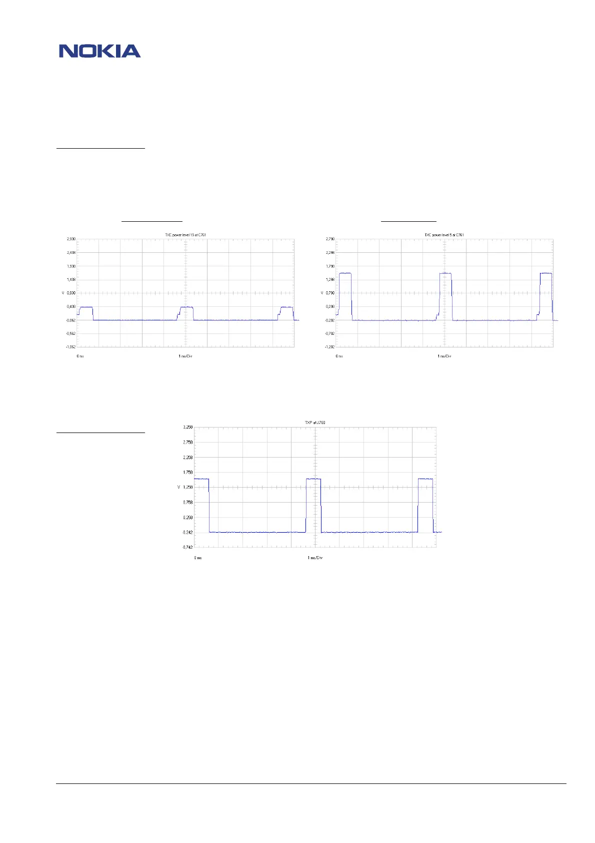
Check TXC at C761, power level 19 and 5. (See picture below)
Oscilloscope settings:
Ampl: 500mV
Time/Div: 10ms/Div
AC/DC/GND: AC
Power level 19
Power level 5
If the TXC signals are not ok, check UEM D200
Check TXP signal at J760. (See picture below)
Oscilloscope settings:
Ampl: 500mV
Time/Div: 1ms/Div
AC/DC/GND: AC
If the TXP signal is not ok, check UPP D400.
Check System Clk = 26 MHz at C752 (See picture at chapter Electrical faults/ Totally dead)
If also the Sys Clk is ok, check following voltages:
Check VR3 = 2.8 VDC at C602 (supply voltage for 26 MHz oscillator G740).
Check VR4 = 2.8 VDC at C601
Check VR5 = 2.8 VDC at C604
Check VR6 (VBB) = 2.8 VDC at C605
Check VR1A (VCP) = 4.7 VDC at C600 (control voltage VC for SHF oscillator).
Check VR7 = 2.8 VDC at C299 (supply voltage VCC for SHF oscillator).
Check VREF01 and VREF02 = 1.35 VDC at R726
If one of the upper described voltages is not ok, check UEM D200.
If all voltages are ok, change Hagar N600.
 Loading...