User’s manual NX-4a Side 6
Connections
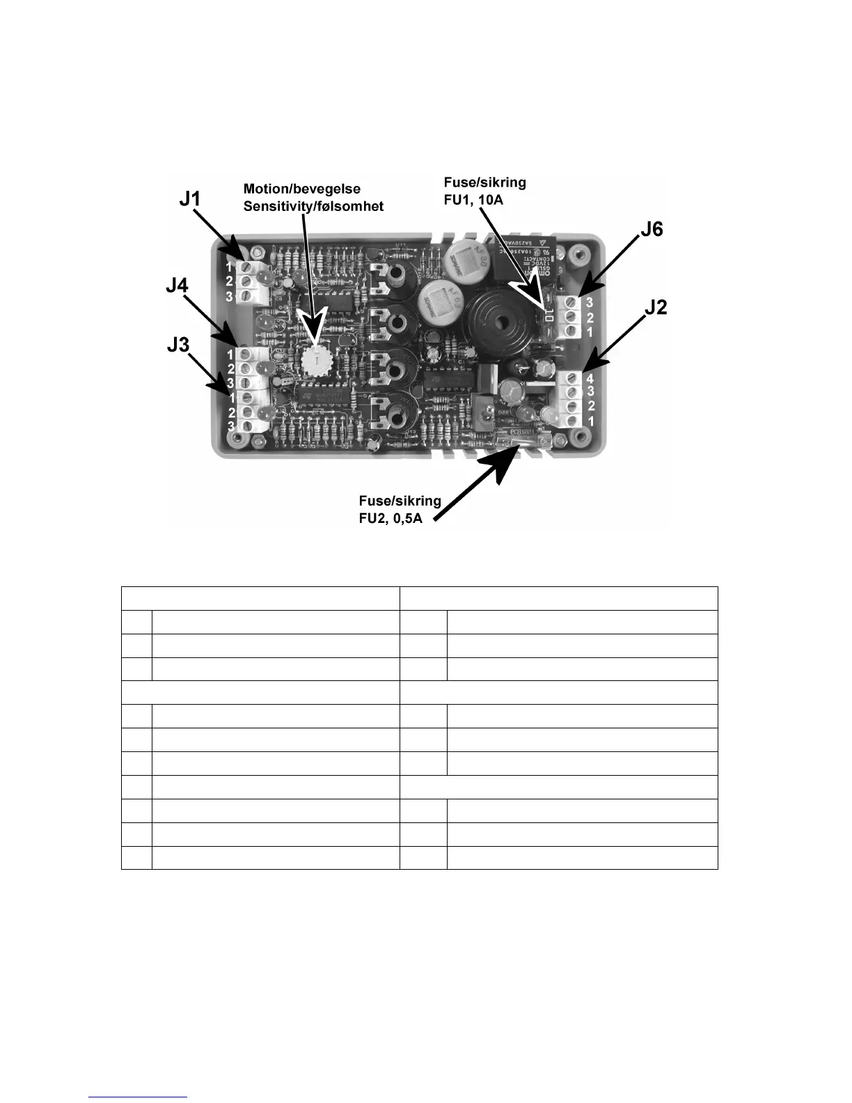
All connections are referred to connectors J1, J2 and so on. Each J-connector has pins numbered from
1 to 3 as shown. Note the small yellow adjustment wheel for the sensitivity setting of the notion
detectors. The illustration shows the NX-4 internals when the front is removed.
The following table shows all the connections. (Se the chapter “Technical specifications” for more
details and electrical data).
Connector J1 Propane sensor Connector J3 Motion detectors with positive signal
1 Red/brown +5V 1 +12V out
2 Green GND/Ground 2 GND / Ground
3 White Signal 3 Signal input, active high/positive
Connector J2 External outputs Connector J4 Motion detectors with negative signal
1 All gas detectors combined 1 +5V out
2 Propane gas separately 2 GND /Ground
3 Motion, delayed 3 Signal input, active low/negative
4 External alarm sounder Connector J6 Power input and lamp output
1 12/24V Power supply
2 GND / Ground
3 12 / 24 V output to external lamps
Note. The external outputs are not fused and will be destroyed if over loaded.
 Loading...