EasyManua.ls Logo

Norcold 983 User Manual

Norcold 983
36 pages
To Next Page IconTo Next Page
Page #1 background imageLoading...
Page #1 background image
900 & 9100
Series
Service Manual & Parts List
for Models
9182 9183
9162 9163
982 983
962 963
Contents
Safety Information . . . . . . . . . . . . . . . 1
Introduction . . . . . . . . . . . . . . . . . . . 2
Specifications . . . . . . . . . . . . . . . . . . 3
Operating Controls . . . . . . . . . . . . . . . 5
Operating Sequence . . . . . . . . . . . . . . 6
Alphanumeric Codes-900 Series . . . . . . . . 7
Flashing LEDs-9100 Series-
(Diagnostic Indicators) . . . . . . . . . . . . . 11
Diagnostics Fault Indicators-900 & 9100 Series 13
Step-by Step Trouble Shooting . . . . . . . . . 15
Internal Control Information - 900 Series . . . . 19
Internal Control Information - 9100 Series . . . 24
Diagnosing Cooling Problems . . . . . . . . . . 29
Component Check-Out Procedures . . . . . . . 31
Procedure for Cleaning Cooling System Flue . . 33
Fuse Replacement Procedure . . . . . . . . . 34
Wiring Pictorials . . . . . . . . . . . . . . . . . 35
618526C (96-05)
Question and Answer IconNeed help?

Do you have a question about the Norcold 983 and is the answer not in the manual?

Norcold 983 Specifications

General IconGeneral
BrandNorcold
Model983
CategoryRefrigerator
LanguageEnglish

Summary

Description of Alphanumeric Codes for 900 Series (Diagnostic Indicators)

A1-LP Gas Ignition Failure

Describes the A1 code for burner ignition failure during initial start-up or re-ignition.

A2-LP Gas Re-Ignition Failure

Details the A2 code for failure to re-ignite the gas burner during normal operation.

A3-Fresh Food Compartment Door Ajar

Explains the A3 code indicating the fresh food compartment door has been left open too long.

A4-AC Mode Selected, AC Power Not Available

Covers the A4 code when AC mode is selected but AC power is not available.

A5-AC Input Voltage Too Low

Describes the A5 code for low AC input voltage, leading to source switching or operation cessation.

A6-AC Input Voltage Too High

Details the A6 code for high AC input voltage, causing source switching or operation cessation.

A7-DC Input Voltage Too Low

Explains the A7 code for low DC input voltage, resulting in lockout of LP Gas and DC heater operation.

A8-DC Input Voltage Too High

Covers the A8 code for high DC input voltage, with code remaining until voltage is corrected.

C1-Burner Failed Ignition and DC Heater Failed

Describes the C1 code for burner ignition and DC heater failure in 3-Way AUTO mode.

C2-AC Heater Output Fault

Details the C2 code for AC heater output fault when the heater should be OFF.

C3-DC Heater Output Fault

Explains the C3 code for DC heater output fault in 3-Way models.

C4-DC Heater Failed Open

Covers the C4 code for DC heater failure (open circuit) where voltage is supplied but no current flows.

C5-Back-Up Operating System

Describes the C5 code indicating the Back-Up Operating System is active due to thermistor failure.

C6-AC Heater Failed Open

Details the C6 code for AC heater failure (open circuit) where voltage is supplied but no current flows.

C7-Flame Sense Circuit Failure

Explains the C7 code for a failure in the flame sense circuit.

C8-AC Heater Failed for Current Out-of-Tolerance

Covers the C8 code for AC heater current being out of tolerance.

C9-DC Heater Failed for Current-Out-Tolerance

Details the C9 code for DC heater current being out of tolerance in 3-Way models.

d1-Inter Control Failure

Explains the d1 code indicating an internal control board failure.

Description of 9100 Series Flashing LED's (Diagnostic Indicators)

Flashing LP Gas LED

Indicates burner ignition failure on initial start-up or gas re-ignition failure.

Flashing AC LED (AC Power Not Available)

Indicates a fault external to controls, with AC mode selected but no AC power.

Flashing AC LED (AC Voltage Issues)

Indicates a fault external to controls, with AC input voltage being too high or too low.

Flashing Battery LED (DC Voltage Issues)

Indicates a fault external to controls, with DC input voltage being too high or too low.

All LED's Flashing (3-Way: Burner/DC Heater Failure)

Indicates burner ignition and DC heater failure in AUTO mode for 3-Way models.

All LED's Flashing (AC Heater Output Fault)

Indicates an AC heater output fault when the AC heater should be OFF.

All LED's Flashing (3-Way: DC Heater Open)

Indicates DC heater failure (open circuit) where voltage is supplied but no current flows.

Flashing Temp Setting LED (Back-Up System)

Indicates the Back-Up Operating System is active due to thermistor failure.

All LED's Flashing (AC Heater Open)

Indicates AC heater failure (open circuit) where voltage is supplied but no current flows.

All LED's Flashing (Flame Sense Failure)

Indicates a failure in the flame sense circuit.

All LED's Flashing (AC Heater Out of Tolerance)

Indicates AC heater current is out of tolerance.
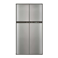
Section 1 - No Display on Display Panel

Section 2 - LP Gas Ignition Failure

Section 3 - Fresh Food Compartment Door Ajar

Section 4 - AC Mode Selected, AC Power Not Available

Section 5 - AC Input Voltage too Low

Section 6 - AC Input Voltage too High

Section 7 - DC Input Voltage too Low

Section 8 - DC Input Voltage too High

Section 9 - Burner Failed Ignition and DC Heater Failed

Section 10 - AC Heater Output Fault

Section 11 - DC Heater Output Fault

Section 12 - DC Heater Failed Open

Section 13 - Back-Up Operating System

Section 14 - AC Heater Failed Open

Section 15 - Flame Sense Circuit Failure

Section 16 - AC Heater Failed for Current Out of Tolerance

Section 17 - DC Heater Failed for Current Out of Tolerance

Section 18 - Internal Control Failure

Internal Control Information - 900 Series

Internal Control Information - 9100 Series

Fuse Replacement Procedure

Related product manuals